35 identify the types of elements in the schematic diagram
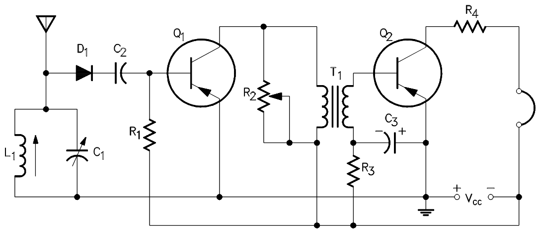
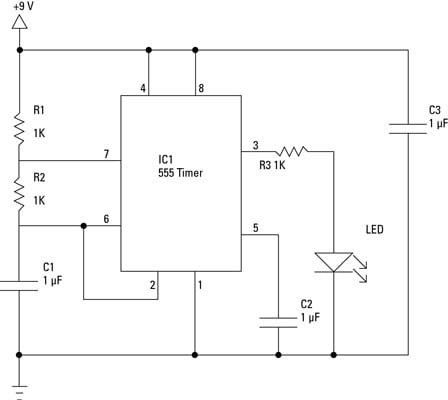
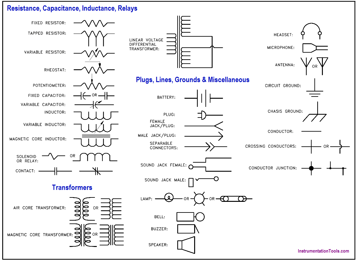
Electronic schematics use symbols for each component found in an electrical circuit, no matter how small. The schematics do not show placement or scale, merely function and flow. From this, the actual workings of a piece of electronic equipment can be determined. Figure 3 is an example of an electronic schematic diagram. 28.09.2021 · The network diagram is a schematic depicting the nodes and connections amongst nodes in a computer network or, more generally, any telecommunications network. Network diagrams are often drawn with professional drawing software tools. There are different types of network diagrams provided by EdrawMax and you can get started with it now! Network diagrams show what the components of a …
Loop Diagram Symbols and P&IDs The table below shows the recommended tag identification letters for instruments and control element designations used in P&IDs and Loop Diagrams. Identification letters First letter Succeeding letters Modifier Measured or initiating variable Readout or passive function Output function Modifier A Analysis Alarm
Identify the types of elements in the schematic diagram
Module 2: Engineering Fluid Diagrams and Prints vi ENABLING OBJECTIVES (cont.) 1.5 IDENTIFY the symbols used on engineering P&IDs for the following basic types of instrumentation: a. Differential pressure cell b. Temperature element A diagram is a symbolic representation of information using visualization techniques. Diagrams have been used since prehistoric times on walls of caves, but became more prevalent during the Enlightenment. Sometimes, the technique uses a three-dimensional visualization which is then projected onto a two-dimensional surface. The word graph is sometimes used as a synonym for diagram. A block diagram provides a means to easily identify the functional relationships among the various components of a control system. The simplest form of a block diagram is the block and arrows diagram. It consists of a single block with one input and one output (Figure 1A). The block normally contains the name of the element (Figure 1B) or the ...
Identify the types of elements in the schematic diagram. Identify the number of and types of elements in this schematic diagram - 1257521 mikayl mikayl 04/27/2016 Physics High School answered • expert verified Identify the number of and types of elements in this schematic diagram 2 How to Identify Old Radios. You've just acquired an old radio, but apart from the manufacturer's name on the front, you don't know a blessed thing about it. Learning more about your radio may satisfy your curiosity, or it may serve a practical purpose such as helping you … A schematic diagram is the road map of the circuit. ... Just as the road map uses symbols to represent the highways, cities, interchanges, and other elements displayed, the schematic diagram uses symbols to represent the components used to make up a circuit. Symbols are used to indicate conductors, ... There are many types of conductors used in ... A schematic diagram is a visual representation of a project plan that is prepared using lines and generic icons to keep the drawing extremely simple and easily understandable. Although schematic diagrams are usually prepared for electrical and electronic projects, they are not limited to those domains and can be created for many other industries such as building and constructions, chemistry ...
Basics 6 7.2 kV 3-Line Diagram : Basics 7 4.16 kV 3-Line Diagram : Basics 8 AOV Elementary & Block Diagram : Basics 9 4.16 kV Pump Schematic : Basics 10 480 V Pump Schematic : Basics 11 MOV Schematic (with Block included) Basics 12 12-/208 VAC Panel Diagram : Basics 13 Valve Limit Switch Legend : Basics 14 AOV Schematic (with Block included) Phase Diagrams • Indicate phases as function of T, Co, and P. • For this course:-binary systems: just 2 components.-independent variables: T and Co (P = 1 atm is almost always used). • Phase Diagram for Cu-Ni system Adapted from Fig. 9.3(a), Callister 7e. (Fig. 9.3(a) is adapted from Phase Diagrams of Binary Nickel Alloys , P. Nash 29.07.2021 · Schematic diagrams are electrical layouts that mainly focus on the basic plan and function rather than its physical location. In contrast, the wiring diagram shows how wires are connected to a device and what will be their exact physical location in a circuit. Let's have a look at their differences with the help of a table. diagrams showing the particles in some samples of materials. The different particles are shown as: Each diagram is meant to show either an element, a compound or a mixture. Decide whether each diagram represents an element, a compound, or a mixture, and explain your reasons. Br C Br Br Br Xe S S S S S S S Kr Ne O Cl H C C C C C H H H H H H C H H H
Input and output elements of a block pictured with lines, and; Relationships between the functions ; Functional sequences and paths for matter and or signals; The block diagram can use additional schematic symbols to show particular properties. Specific function block diagram are the classic functional flow block diagram, and the Function Block Diagram (FBD) used in the design of … Chemists use schematic drawings to describe how different elements interact with each other to create a product. Pictorial diagrams, block diagrams, and wiring diagrams are the simplest diagrams and are best suited for the average homeowner or handyman tackling a weekend project. The diagrams include enough detail to identify components and to ... CREATE THIS TEMPLATE . For more matrix and quadrant chart examples, visit our post on the 20+ SWOT templates, examples and best practices. Return to Types of Diagrams list . Venn diagram. Venn diagrams look like two or more overlapping circles, with text in each section of each circle that describes the categories. With these diagrams, you can quickly communicate differences and similarities ... Use Case Diagram. As the most known diagram type of the behavioral UML types, Use case diagrams give a graphic overview of the actors involved in a system, different functions needed by those actors and how these different functions interact.. It's a great starting point for any project discussion because you can easily identify the main actors involved and the main processes of the system.
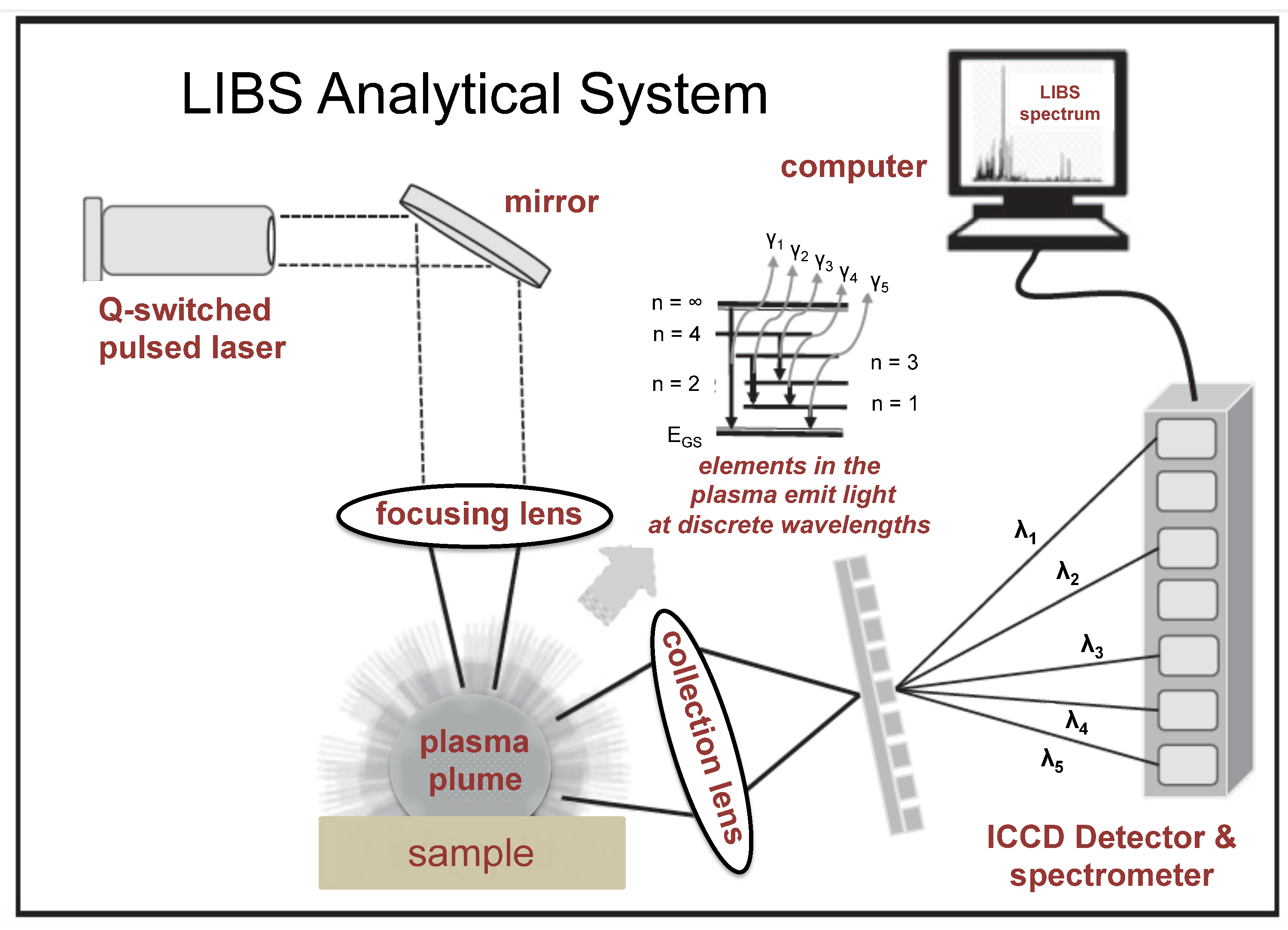
Minerals Free Full Text Laser Induced Breakdown Spectroscopy An Emerging Analytical Tool For Mineral Exploration Html
Types of Fluid Power Diagrams. Several kinds of diagrams can be used to show how systems work. With an understanding of how to interpret Figure 29, a reader will be able to interpret all of the diagrams that follow. A pictorial diagram shows the physical arrangement of the elements in a system.
Redpandascience Files Wordpress Com
Network diagrams can be used to represent virtually any network, which means that there's a lot of variety. Network diagrams vary in two important ways: by the type of network they represent and by network topology, or the arrangement of components. Below are a few examples, and you can always visit our network diagram example library for more.
How To Read Oil And Gas P Id Symbols Kimray
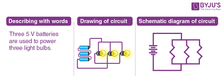
A schematic, or schematic diagram, represents the elements of a system with abstract and graphic symbols instead of realistic pictures.A schematic diagram focuses more on comprehending and spreading information rather than doing physical operations. For this reason, a schematic usually omits details that are not relevant to the information that it intends to convey and may add simplified ...
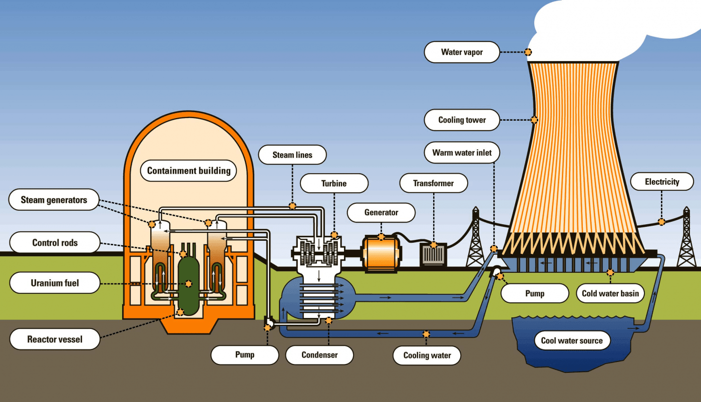
What Are The Different Components Of A Nuclear Power Plant Foro Nuclear
When developing a circuit diagram or schematic, it is necessary to identify the individual components. This is particularly important when using a parts list as the components on the circuit diagram can be cross related to the parts list or Bill of Materials.
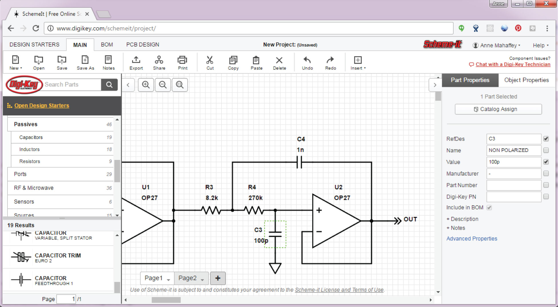
The Schematic Diagram A Basic Element Of Circuit Design Analog Devices
Identify elements of an affinity diagram • Define and discuss tree diagrams, matrix diagrams, PDPC charts, and activity network diagrams • Create interrelationship diagrams Module 6 - Control Charts This module begins with a discussion about maintaining process improvement solutions once they are in place, but the primary focus of this module is on the creation and use of control charts ...

1 391 Electrical Circuit Diagram Stock Photos Pictures Royalty Free Images Istock
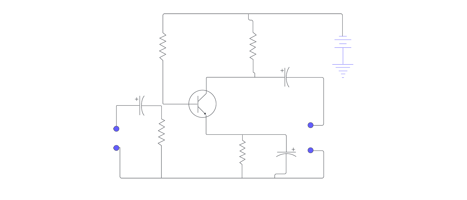
A circuit diagram is a simplified representation of the components of an electrical circuit using either the images of the distinct parts or standard symbols. It shows the relative positions of all the elements and their connections to one another. It is often used to provide a visual representation of the circuit to an electrician.

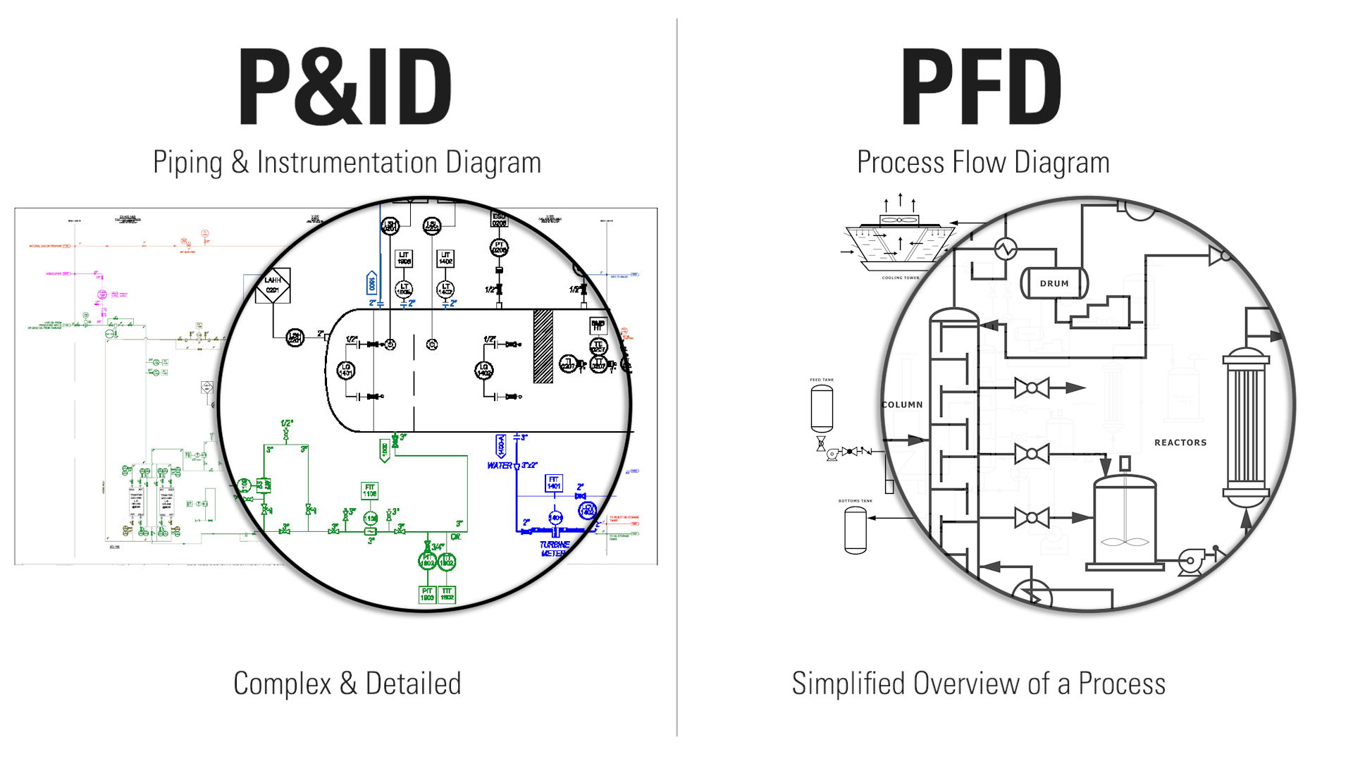
Difference Between Pictorial And Schematic Diagrams Lucidchart Blog
Identify the types of elements in the schematic diagram give the number of each types. Identify the types of elements in the schematic diagram give the number of each types. Categories Uncategorized. Leave a Reply Cancel reply. Your email address will not be published. Required fields are marked *

Chemoresistive Materials For Electronic Nose Progress Perspectives And Challenges Park 2019 Infomat Wiley Online Library
The class diagram is one of the types of UML diagrams which is used to represent the static diagram by mapping the structure of the systems using classes, attributes, relations, and operations between the various objects. A class diagram has various classes; each has three-part; the first partition contains a Class name which is the name of the ...

Identify The Various Elements Of The Circuit Shown Below What Does The Bigger Line Of Element By Brainly In
Schematic Reading Tips Identify Blocks. Truly expansive schematics should be split into functional blocks. There might be a section for power input and voltage regulation, or a microcontroller section, or a section devoted to connectors. Try recognizing which sections are which, and following the flow of circuit from input to output.
Circuit Diagram And Its Components Explanation With Circuit Symbols
Electrician Circuit Drawings and Wiring Diagrams Youth Explore Trades Skills 3 Pictorial diagram: a diagram that represents the elements of a system using abstract, graphic drawings or realistic pictures. Schematic diagram: a diagram that uses lines to represent the wires and symbols to represent components.
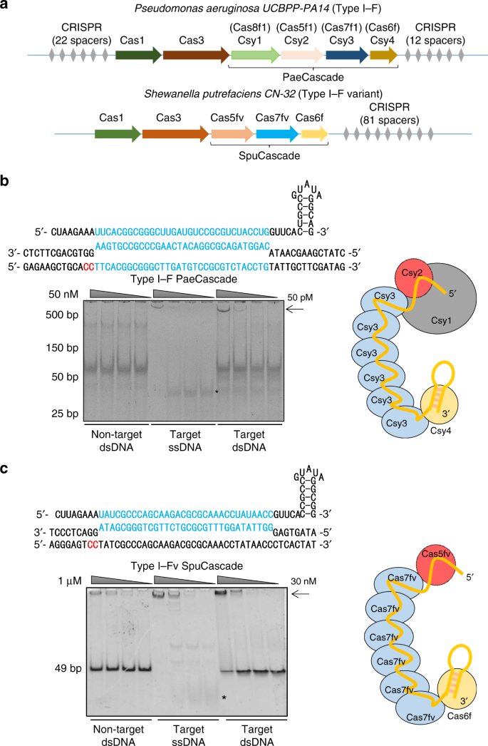
Repurposing Type I F Crispr Cas System As A Transcriptional Activation Tool In Human Cells Nature Communications
Diatomic Element-Found only combined in nature with itself.-7 diatomic elements. "BrINClHOF" Br 2 I 2 N 2 Cl 2 H 2 O 2 F 2 Monatomic element-Found alone in nature.-Stable and inert (unreactive). Substances Elements : made of ONE TYPE of atom with their own unique properties. Properties Elements CANNOT be broken down chemically or physically.

Circuit Element An Overview Sciencedirect Topics
Particle Diagrams - Representing Matter •Elements and compounds can be represented using particle diagrams. •A particle diagram is a box in which coloured balls are draw to represent atoms or molecules. •These diagrams can represent elements and compounds, as well as their molecular composition by the types of balls and how they are ...
1
Different Types of Electrical Diagrams and Drawing. In Electrical and Electronics Engineering, we use different types of drawings or diagrams to represent a certain electrical system or circuit.These electrical circuits are represented by lines to represent wires and symbols or icons to represent electrical and electronic components.It helps in better understanding the connection between ...

Posttranslational Regulation Of Multiple Clock Related Transcription Factors Triggers Cold Inducible Gene Expression In Arabidopsis Pnas
13.05.2014 · schematic diagram, the symbolic elements are arranged to be easily interpreted by the viewer. Power system relaying has unique requirements for long term accuracy to serve maintenance and troubleshooting needs. The facilitation mentioned above for tracing circuits and understanding functions is especially important to the requirements for
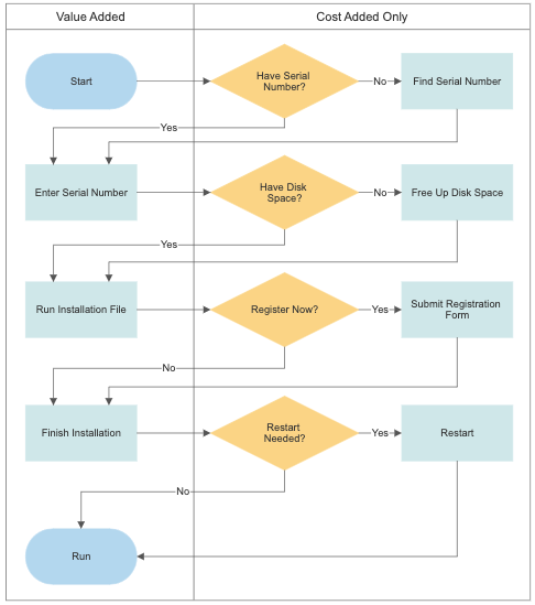
Different Types Of Flowcharts And Flowchart Uses
Line Diagrams A line (ladder) diagram is a diagram that shows the logic of an electrical circuit or system using standard symbols. A line diagram is used to show the relationship between circuits and their components but not the actual location of the components. Line diagrams provide a fast, easy understanding of the connections and
Electronic Diagrams Prints And Schematics Instrumentation Tools
To filter a diagram, you may be able to adapt whatever filtering interface you already have in your system. Chapter 6, Data Retrieval: Filter and Browsing, covers filtering. When there are many elements or when the diagram is used to analyze problems, it may make sense to provide a query-on-query option. In other words, rather than asking users ...

Project Planning Control Handbook Nasa
Pictorial Diagrams •Also known as label or line diagrams -Intended to show actual internal wiring •Shows all control panel components as a blueprint •Components not shown in the control panel are shown outside the panel and labeled •Factual diagram -Consists of a pictorial diagram along with a schematic diagram
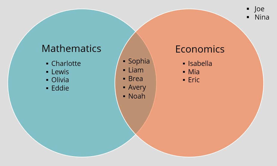
Venn Diagram Overview Symbols Examples Benefits
A circuit diagram behind a circuit board. kr7ysztof / Getty Images. Schematic diagrams are typically associated with electrical circuits. Also called wiring diagrams or circuit diagrams, these diagrams show how the different components of a circuit are connected.In these diagrams, lines represent connecting wires, while other elements like resistors, lamps, and switches are represented by ...
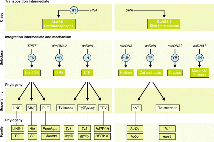
Ten Things You Should Know About Transposable Elements Genome Biology Full Text
The Elements of User Experience: User-Centered Design for the Web and Beyond, Second Edition . × Close Log In. Log in with Facebook Log in with Google. or. Email. Password. Remember me on this computer. or reset password. Enter the email address you …
Electronic Components And Circuit Diagram Symbols
Types and Uses of Block Diagrams. A block diagram provides a quick, high-level view of a system to rapidly identify points of interest or trouble spots. Because of its high-level perspective, it may not offer the level of detail required for more comprehensive planning or implementation.

The Schematic Diagram A Basic Element Of Circuit Design Analog Devices
For each electron shell atom diagram, the element symbol is listed in the nucleus. The electron shells are shown, moving outward from the nucleus. The final ring or shell of electrons contains the typical number of valence electrons for an atom of that element. The element atomic number and name are listed in the upper left.

Active And Passive Circuit Elements What S The Difference Electrical4u
A block diagram provides a means to easily identify the functional relationships among the various components of a control system. The simplest form of a block diagram is the block and arrows diagram. It consists of a single block with one input and one output (Figure 1A). The block normally contains the name of the element (Figure 1B) or the ...
Redpandascience Files Wordpress Com
A diagram is a symbolic representation of information using visualization techniques. Diagrams have been used since prehistoric times on walls of caves, but became more prevalent during the Enlightenment. Sometimes, the technique uses a three-dimensional visualization which is then projected onto a two-dimensional surface. The word graph is sometimes used as a synonym for diagram.
C8ivyulttvgqfm
Module 2: Engineering Fluid Diagrams and Prints vi ENABLING OBJECTIVES (cont.) 1.5 IDENTIFY the symbols used on engineering P&IDs for the following basic types of instrumentation: a. Differential pressure cell b. Temperature element
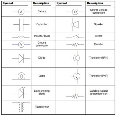
Electronics Schematics Commonly Used Symbols And Labels Dummies

Sustainability Free Full Text Micro Encapsulated Phase Change Materials A Review Of Encapsulation Safety And Thermal Characteristics Html
Electronics Schematics Commonly Used Symbols And Labels Dummies
1
Difference Between Pictorial And Schematic Diagrams Lucidchart Blog

Mapping The Cis Regulatory Architecture Of The Human Retina Reveals Noncoding Genetic Variation In Disease Pnas

Structure Diagram An Overview Sciencedirect Topics

Types Of Electronic Diagrams

Chromatin Architecture Reveals Cell Type Specific Target Genes For Kidney Disease Risk Variants Bmc Biology Full Text
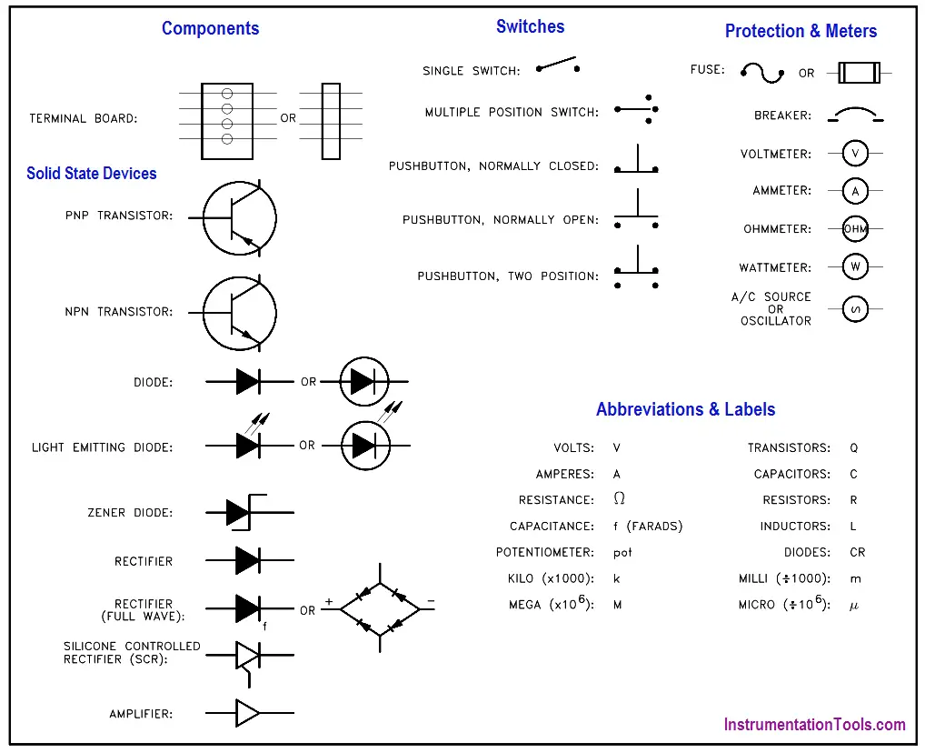
Electronic Diagrams Prints And Schematics Instrumentation Tools
Electronic Diagrams Prints And Schematics Instrumentation Tools
0 Response to "35 identify the types of elements in the schematic diagram"
Post a Comment