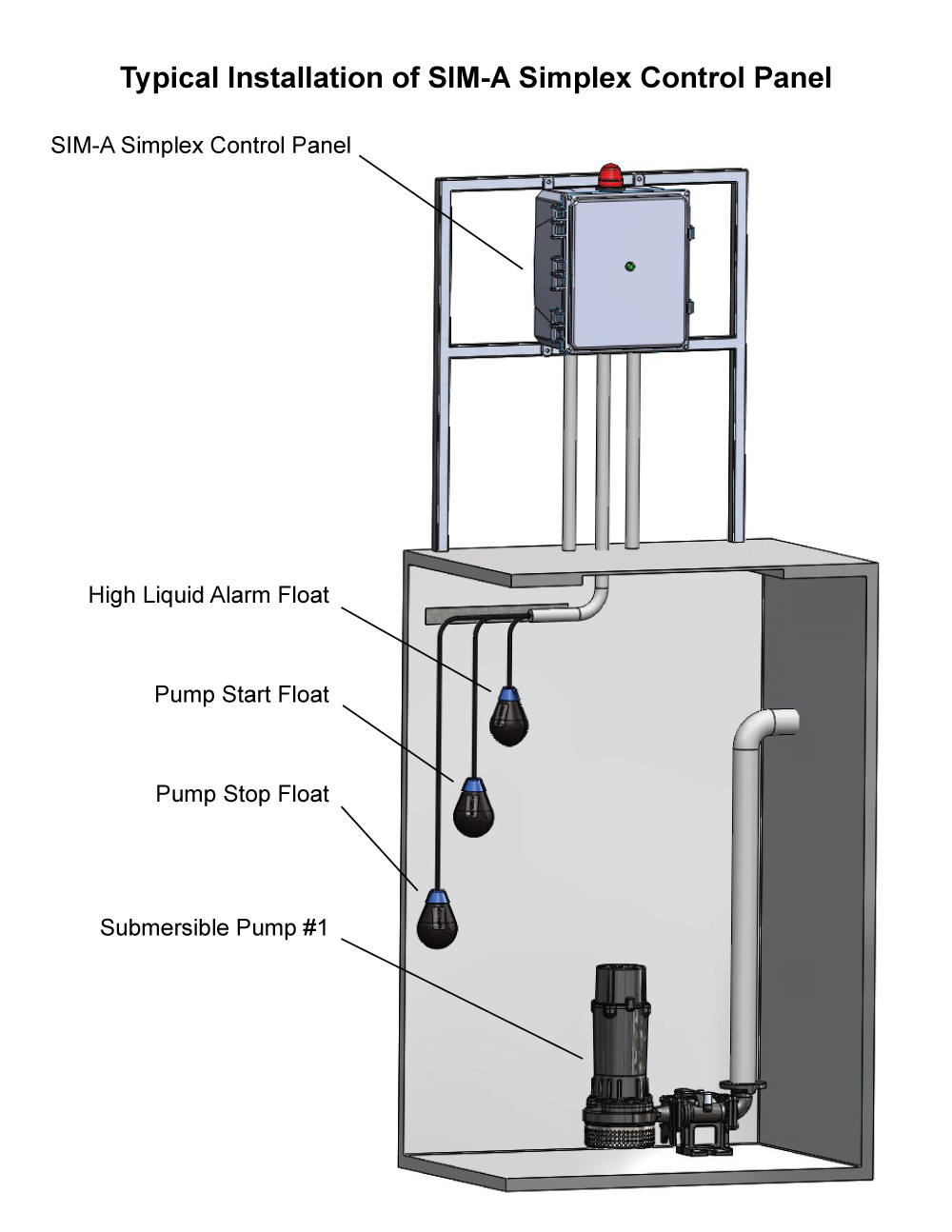
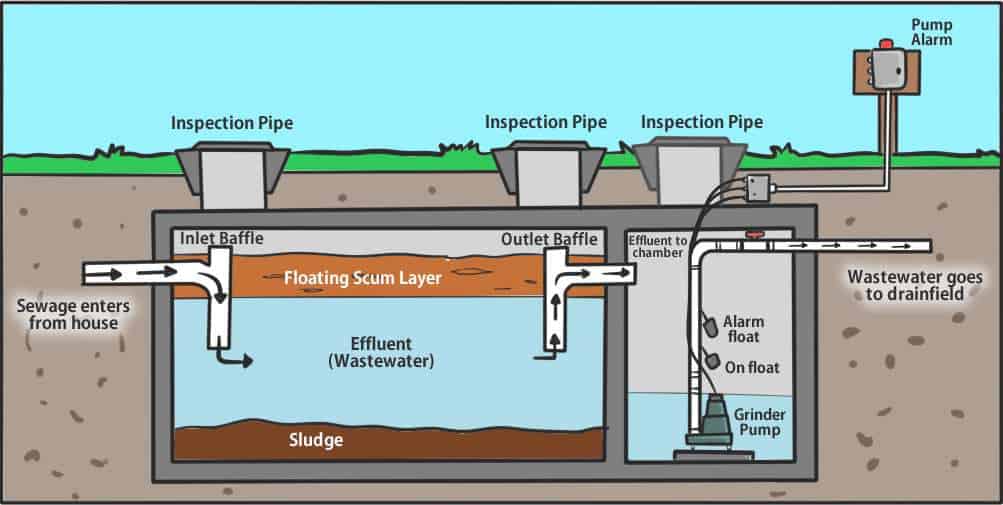
35 septic pump wiring diagram
The basic 3 way switch wiring diagram this entry was posted in outdoor wiring diagrams and tagged 2 speed pump 230 volt pump breaker disconnect how to wire a pump pump wiring wiring diagram. 2 wire submersible well pump wiring diagram webtor 2 wire submersible well pump wiring diagram. Square d pressure switch wiring diagram square d pumptrol wiring diagram electric. A wiring diagram is a streamlined traditional photographic representation of an electric circuit. Square d pumptrol fsg well tank pressure switches are the industry standard for household well installations.
Take it through the plastic mounting tabs on the clamp. After this, take the pipe clamp lower and take it to the discharge pipe of the effluent pump. After a while, it will reach the mentioned height in the manual of the septic float switch. Hold the pipe clamp and tighten it loosely. Use a screwdriver here.
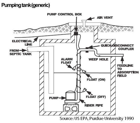
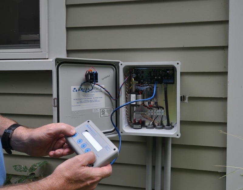
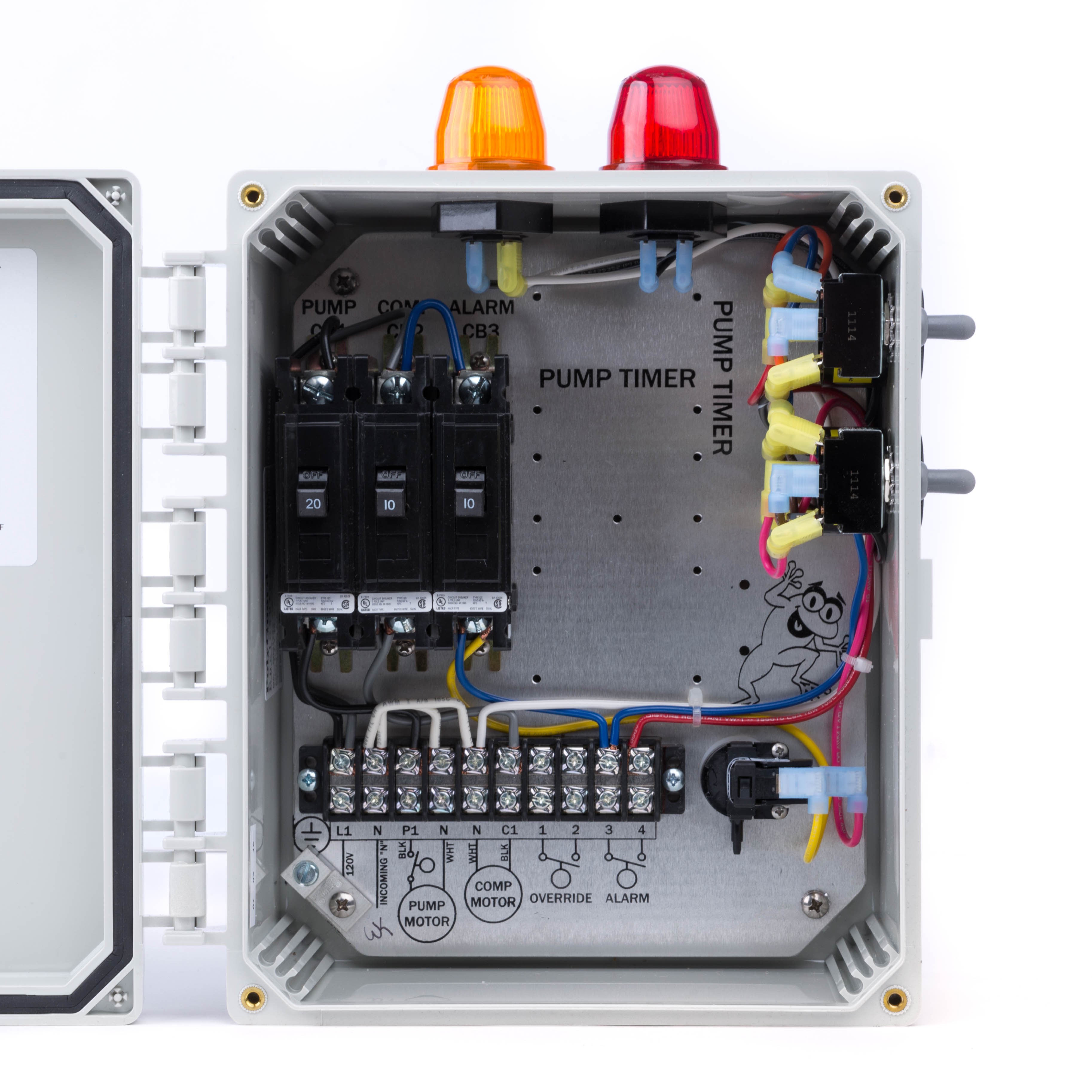
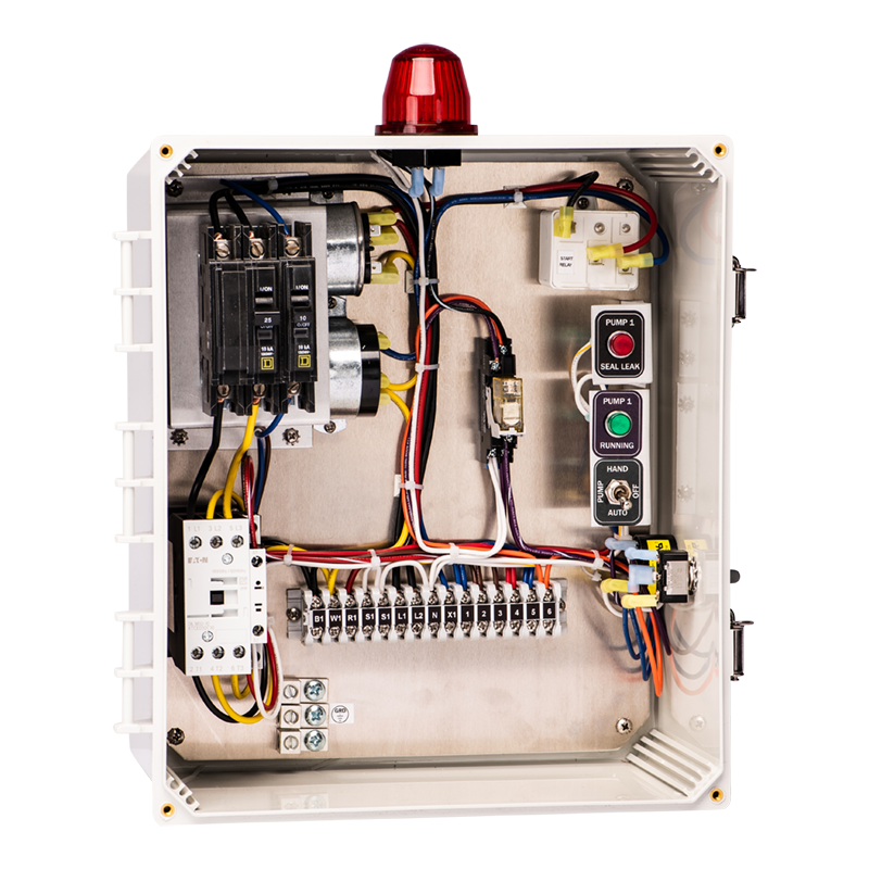
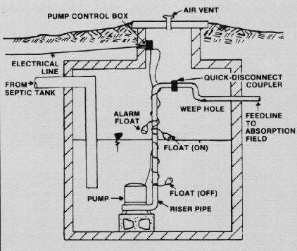
Septic pump wiring diagram
Jun 17, 2019 - Enclosure Box I Used: https://amzn.to/2PNw21mAudible Alarm with Float: https://amzn.to/2PKmnslSewage Septic Pump: ... Septic Pump Wiring Diagram Best Water And Throughout Duplex Control Panel In Well Pump Pressure Switch Submersible Well Pump Well Pump . Homemade Surface Grinder Homemade Tools Diy Metal Woodworking Workbench . In diagram, grinder, surface, wiring. Leave a Reply Cancel reply. 39 Payne Heat Pump Wiring Diagram; 37 Dodge Ignition Wiring Diagram; 42 Rock Cycle Diagram Worksheet; 39 Dot Diagram For Phosphorus; 38 What Is A Logic Diagram; 42 Kenwood Kdc Bt310u Wiring Diagram; 43 2006 Pontiac G6 Exhaust Diagram; 43 Orbital Diagram Of Fe; 42 2006 Honda Civic Belt Diagram; 40 Animal Cell Diagram Project; 39 X1 Pocket Bike ...
Septic pump wiring diagram. Electrical Engineering Design And Drawing Book Pdf Best Of Electrical Wiring Diagra Trailer Wiring Diagram Electrical Wiring Diagram Electrical Circuit Diagram. SAVE IMAGE. How A Septic System Works Lovely Grease Trap Pumping Septic System Septic Tank Systems Septic Tank Repair ... Top 9 Best Submersible Deep Water Pumps In 2020 Water Pumps ... Diesel Truck Lanes Closed. I normally fuel at truck lanes. Today, I was traveling from Flagstaff to Grants, N.M. I need DEF too, which I only buy at truck stops since it's so easy to pump and cheaper. I have the TSD fleet card which showed a TA just west of Gallup. Exited, pulled in and discovered every single truck lane blocked with orange cones. 24 3 Phase Dol Starter Control And Power Wiring Diagram Water Pump Controller With Float Switch Youtube Electrical Projects Water Pumps Electrical Jobs . Septic Pump Float Switch Wiring Diagram Tank Fresh Amazing Gallery The Best Electrical Circuit Electrical Circuit Diagram Electrical Wiring Diagram Boat Wiring . Sump pumps are essential. Single-phase submersible pump control box wiring diagram - 3 wire submersible pump wiring diagram. In the submersible pump control box, we use a capacitor, a resit-able thermal overload, and a DPST switch (double pole single throw). The wiring connection of the submersible pump control box is very simple.
Please note: The information below refers to 115V pumps and wiring. We recommend using a ... Below is a diagram of what is described in the paragraph above. Plumbing diagram for house on slab. A rough in plumbing diagram is a sketch for all the plumbing pipes pipe fittings. These plumbing sewer pipes should be checked anytime there had been significant foundation movement or foundation repair. If its a rural home the main sewer line runs to a septic tank. Basic Safe Electric Fuel Pump Wiring Diagram This is the basic wiring diagram for SAFE electric fuel pump wiring. The diagram is color coded per circuit and only a few things may need to be said. Fuel pump wiring for the RED circuit is generally going to carry a much higher current than the relay. So use a larger gauge wire for lower voltage drop. 38 53 Ft Trailer Loading Diagram. Follow standard procedures to ensure proper weight distribution in a semi trailer. Step 1. Have the proper loading equipment, such as a hand truck or forklift, on hand to ensure that cargo can be moved in and out of the trailer easily.
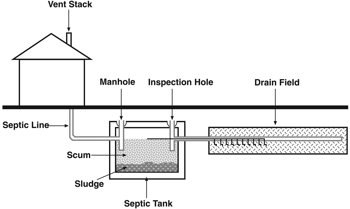
Septic tank lateral lines diagram. #5 Septic Tank or Line Leak.. If you have a uniquely healthy patch of vegetation in the said area, it could be an indication that your septic tank has a leak or that your lateral lines are receiving far too much wastewater from the septic tank and are overly-saturating your yard. Psq500 Ps600 Ps1400 Installation Wire Diagrams Manualzz. Lithonia Lighting Ps300qd Installation Instructions. Psq500qd Mvolt Emergency Ballast. Ps600dw Emergency Ballast. Psq500dw Power Sentry. Psl600 Power Sentry Manualzz. ... Septic Pump Alarm Wiring Diagram. Wiring Diagram. Post navigation READ Septic Pump Float Switch Wiring Diagram Gallery. You will be able to learn specifically if the tasks ought to be completed which makes it much simpler to suit your needs to. Meyer Light Wiring Diagram One of the most difficult automotive fix tasks that a mechanic or repair shop can put up with is the wiring or rewiring of a cars electrical ... This diagram applies to all types of installations (i.e. basement, slab, crawl space, outside). …. How Does a Hot Water Recirculating Pump Work? The hot water recirculating pump, as the name indicates, creates a loop for the hot water to move across all the fixtures, taps, and faucets in your water circulation system.
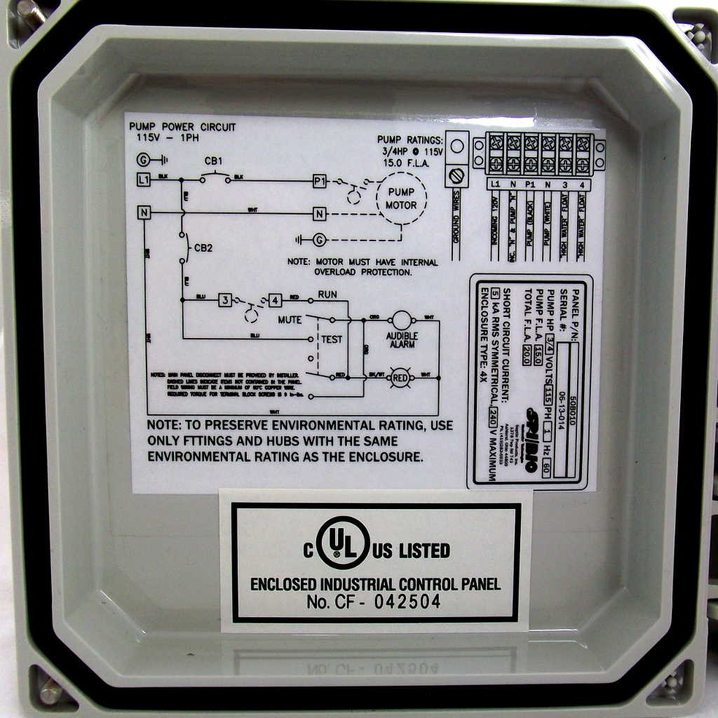
Single Phase Water Pump Control Panel Wiring Diagram from imaginetech.in. Simply provide us with the fla and voltage of your pumps and septic solutions will provide you with. Single phase submersible pump control panels are widely used for domestic and industrial sectors. Control panel circuit breaker (short circuit protection).
Yamaha v star 650 starter relay location off 66 www durvamachinery com 2007 signal continuous starbike forum wiring diagrams 2010 photo and reviews all moto net 1100 fuel pump 69 medpharmres xs650 schematic chopper 2018 custom xvs65gcw electrical 1 parts oem diagram for motorcycles 2003 aftermarket carburetor promotions off65 2001 xvs650n ...
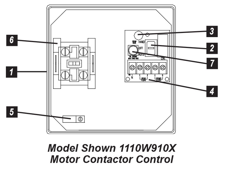
Sje Rhombus Sje Rhombus Model 111 Simplex Single Phase Motor Contactor Or Pump Switch Control 120 208 240vac Sje111
Basement Electrical Wiring Diagram - wiring diagram is a simplified enjoyable pictorial representation of an electrical circuit. It shows the components of the circuit as simplified shapes, and the skill and signal friends along with the devices. A wiring diagram usually gives suggestion virtually the relative slant and conformity of devices.
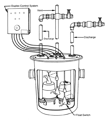
2 Jan 2002 — Connect the wires coming from the pumps to the pump terminals. Refer to the panel wiring diagram for the correct terminal connections for your ...10 pages
Diagram 1997 jeep wrangler fuel pump wiring full version hd quality 1998 tj guide or forum ignition switch menulisitukerjaaku pin on 1987 yj i need a engine for cherokee with cruise control help diagrams headlight headlamp is there relay heater problem am working 2 5 it not charging battery ok alt was removed and tested have ign 97… Read More »

We Remodel A Home And Found The Electrical Bill 50 Kwatts Per Day Before Even Moving In There Was No One Living There
Hi all, sorry for the panic. I have rewired my septic tank submersible pump and air blower so that I can incorporate a digital timer switch. It's a Müller SC 28.21 pro4 timer like this: https://charter-controls.com/products/sc28-21pro4-230vac/ However, I have wired the L and N input but I can't seem to get any power output to the air blower or pump, despite the timer being set as "on". So the question I have is how am I supped to wire this digital timer switch? I assumed it was L+N in and the...
Diagram wiring for piaa lights how to install 520 series 6 in rs800 halogen building light harness 540 oem fogs bmw luxury touring community 510 4. The relay already exists. It's the box in the PIAA wiring diagram you posted, so you don't need another relay. The wiring diagram that @azsean posted will have the lower light illuminated all the time.
15 Septic Tank Float Switch Wiring Diagram. The float switch moves with the water level in the tank and this determines when the pump turns on one leg of the float switch will connect to the hot wire from the panel; It is used to detect the level of liquid within a tank. This toyota rav4 electrical wiring diagrams and technical specification ...
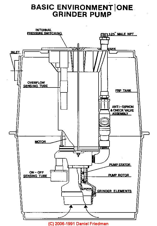
Septic Pumps Sewage Ejector Pumps Septic Grinder Pumps Septic Effluent Pumps Sump Pumps Buy Install Maintain Repair Guide
39 Payne Heat Pump Wiring Diagram; 37 Dodge Ignition Wiring Diagram; 42 Rock Cycle Diagram Worksheet; 39 Dot Diagram For Phosphorus; 38 What Is A Logic Diagram; 42 Kenwood Kdc Bt310u Wiring Diagram; 43 2006 Pontiac G6 Exhaust Diagram; 43 Orbital Diagram Of Fe; 42 2006 Honda Civic Belt Diagram; 40 Animal Cell Diagram Project; 39 X1 Pocket Bike ...
Septic Pump Wiring Diagram Best Water And Throughout Duplex Control Panel In Well Pump Pressure Switch Submersible Well Pump Well Pump . Homemade Surface Grinder Homemade Tools Diy Metal Woodworking Workbench . In diagram, grinder, surface, wiring. Leave a Reply Cancel reply.
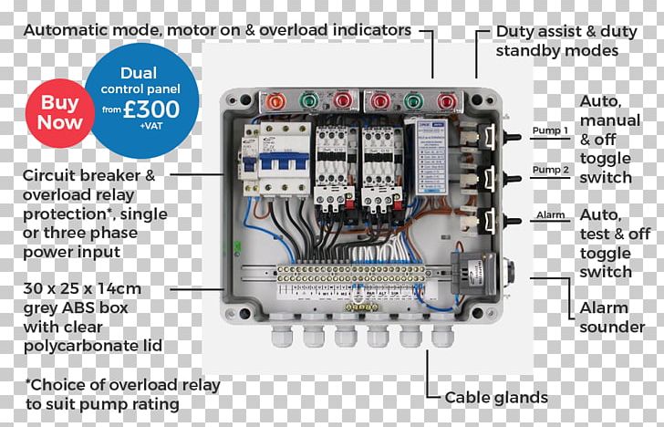
Submersible Pump Wiring Diagram Control Panel Pumping Station Png Clipart Circuit Component Circuit Diagram Electrical Wires
Jun 17, 2019 - Enclosure Box I Used: https://amzn.to/2PNw21mAudible Alarm with Float: https://amzn.to/2PKmnslSewage Septic Pump: ...
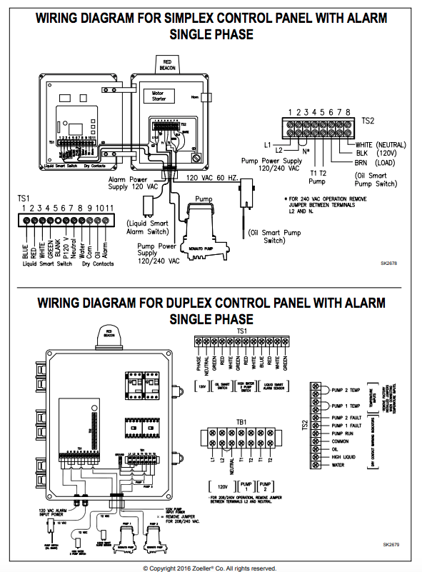
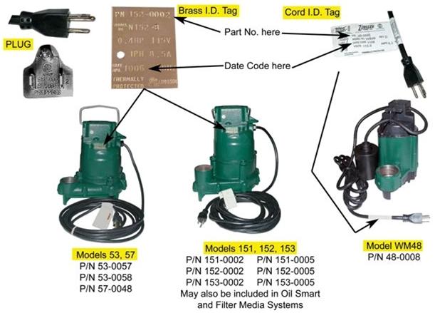
Zoeller 940 0014 Oil Guard Elevator Pump Package With Smart Switch Alarm And N161 Pump 1 2 Hp 115 Volts 1 Phase 15 Amps 100 Gpm Max 56 Ft Max Head 6 Ft Cord
How Do I Wire A 110 Float Switch To A 220 Pump Its A 220 V 1 2 Hp Franklin Motor On The Pump I Have A 400 Ft Run On







0 Response to "35 septic pump wiring diagram"
Post a Comment