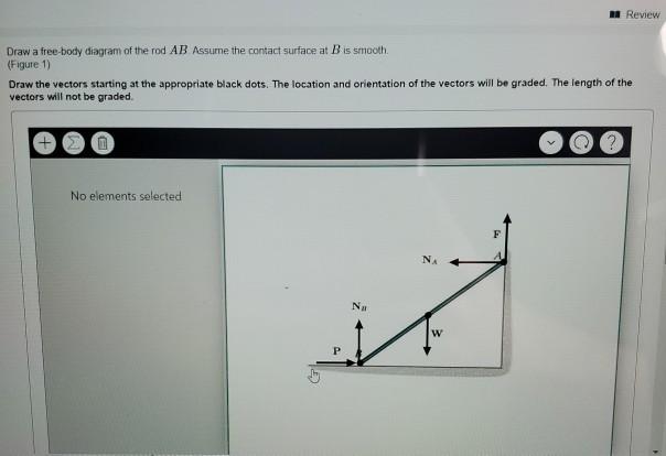
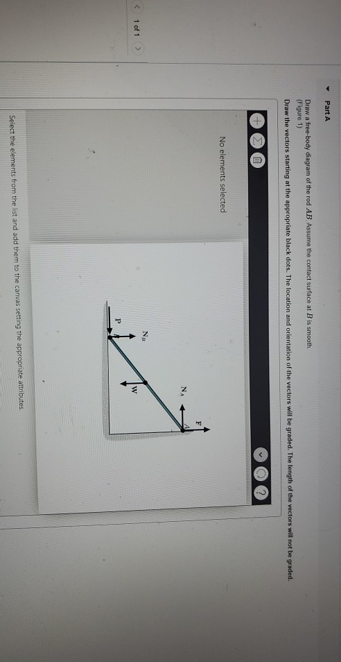
36 draw a free-body diagram of the rod ab. assume the contact surface at b is smooth.
AB and rests on a moving belt. Knowing that m s = 0.25 and m k = 0.20, determine the magnitude of the horizontal force P that should be applied to the belt to maintain its motion (a) to the right, (b) to the left. SOLUTION We note that link Drawing Free-Body Diagrams. Free-body diagrams are diagrams used to show the relative magnitude and direction of all forces acting upon an object in a given situation. A free-body diagram is a special example of the vector diagrams that were discussed in an earlier unit. These diagrams will be used throughout our study of physics.
• Create a free-body diagram for the complete frame and solve for the support reactions. • Define a free-body diagram for member BCD. The force exerted by the link DE has a known line of action but unknown magnitude. It is determined by summing moments about C. • With the force on the link DE known, the sum of forces in the x and y directions
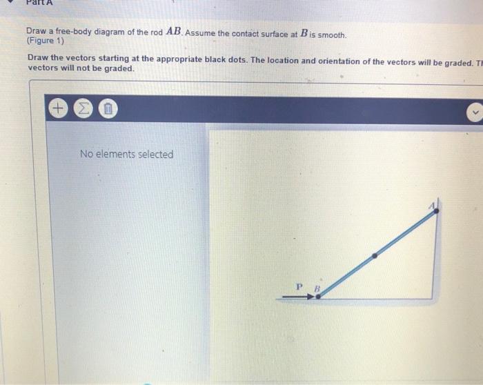
Draw a free-body diagram of the rod ab. assume the contact surface at b is smooth.
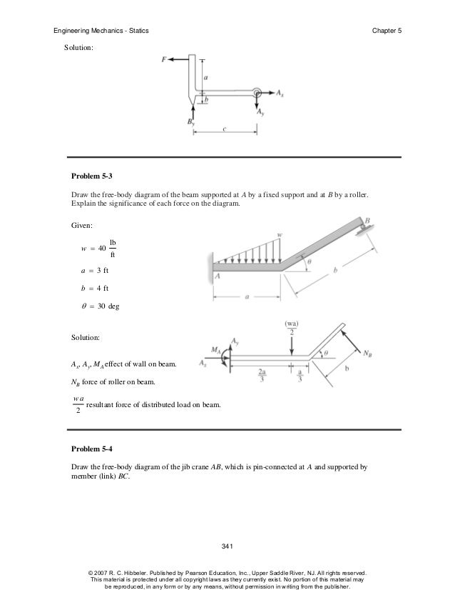
Examples of drawing free-body diagrams. To better understand how to draw free-body diagrams using the 3 steps, let's go through several examples. Example 1. A box is pushed up an incline with friction which makes an angle of 20 ° with the horizontal. Let's draw the free-body diagram of the box. The first step is to sketch what is happening: Free-Body Diagram: For no motion, reaction at . A must be downward or zero; smallest distance a for no motion corresponds to A = 0. + SM B = 0 200 150 150 50 200 300 0: ( )( ) ( ) ( )( ) ( )N mm N N mm mm- - + +a a A= A a = (200 20000- ) 300 The problem can be solved by considering segment AB, which does not involve the support reactions at C. Free-Body Diagram.The x, y, z axes are established at B and the free-body diagram of segment AB is shown in Fig. 1-8b.The resultant force and moment components at the section are assumed to act in
Draw a free-body diagram of the rod ab. assume the contact surface at b is smooth.. Draw a free-body diagram of the rod AB. Assume the contact surface at B is smooth. Determine the minimum force P to prevent the 28-kg rod AB from sliding. rod = 10 kg. The pendulum has an angular velocity of 3 rad/s when = 45 and the external moment of 50 N m. Find: The reaction at the pin O when = 45 . Plan: Draw the free body diagram and kinetic diagram of the rod and sphere as one unit. Then apply the equations of motion. W. Wang 18 a) Draw the vectors starting at the appropriate blue dots. b) Determine the minimum force P to prevent the 20 kg rod AB from sliding, the contact surface at B is smooth, whereas the coefficient of ... Draw the free-body diagram of the bar, which has a 75 3mm in. negligible thickness and smooth points of contact at A, B, 30 and C. Explain the significance of each force on the 5 in.mm 125 diagram. (See Fig. 5-7b.)
To construct a free-body diagram for a rigid body or any group bodies considered as a single system, the following steps should be performed: Draw Outlined Shape. Imagine the body to be isolated or cut "free" from its COnstraints and connections and draw (sketch) its outlined shape. Show All Forces and Couple Moments. diagram for one object, there is an opposite force vector that appears in the free-body diagram for another object. An example involving two blocks on a table is shown in Fig. 4.1. If a person applies a force F to the left block, then the two free-body diagrams are shown (assume there is no friction from the table). To draw a free body diagram, start by sketching a simple representation of the body you want to make the diagram of, like a square to represent a box. Next, draw arrows on the shape that show the forces acting on the object. For example, draw a downward arrow to signify the weight of the object, since gravity pulls the object down. 10. We now draw a free-body diagram for a section at A. 45˚ 1500 N AB DA 11. F! y = 0 AB sin 45˚- 1500!F x = 0 = AB cos 45˚- DA 12. Solving simultaneous equations gives AB = 2121 N, DA = 1500 N. 13. We now draw a free-body diagram for a section at D. 45˚ 1500 N 2121 N BD D B C A 4500 N
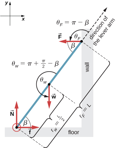
horizontal surface. A horizontal force Pis applied to the right on the block. The free body diagram of the block is shown in the gure below right. In this free body diagram fand N are the friction and normal components, respectively, of the reaction force of the ground on the block. From this FBD, we have the following equilibrium equations: X F Draw free-body force diagram Apply Newton's Second Law in Radial and vertical directions Solve for tensions in two strings: Increase then upper string breaks first. kˆ:T upper cos45 −T lower cos45 −mg=0⇒T upper −T lower =2mg rˆ:−T upper sin45 −T lower sin45 =−mssin45 ω2⇒T upper +T lower =msω2 T upper =m(sω2+2g)/2 T lower Free-body diagram Assume that only the rollers located at the bottom of the rod are used for support. For each roller at B & C, the reaction is perpendicular to the contact surface. Solution The reaction at A is perpendicular to the wall as the wall is smooth. Equations of Equilibrium + → Σ F x = 0: C y' sin 30 ο + B y' sin 30 ο - A ... Smooth Surface Contact ! If you were to push on a hard smooth surface, think about how it would push back Hard Smooth Surface 24 Free Body Diagrams Wednesday, October 3, 2012 New Support Conditions Smooth Surface Contact ! We have a rod/stick/something resting on a smooth surface (smooth is important here) Hard Smooth Surface
Solved Draw A Free Body Diagram Of The Rod Ab Assume The Chegg Com
Draw the free-body diagram of member ABCwhich is supported by a smooth collar at A, rocker at B, and short link CD. Explain the significance of each force acting on the diagram. (See Fig. 5-7b.) SOLUTION. The Significance of Each Force: is the smooth collar reaction on member ABC. is the rocker support Breaction on member ABC.
Uobabylon Edu Iq
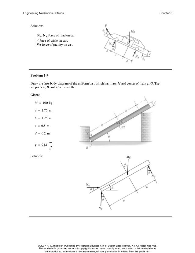
Given: M = 20 gm a = 75 mm b = 200 mm θ = 40 deg Solution: A x , A y , NB force of glass on rod. M(g) N force of gravity on rod. Problem 5-7 Draw the free-body diagram of the "spanner wrench" subjected to the force F. The support at A can be considered a pin, and the surface of contact at B is smooth.
Answered The Smooth Uniform Rod Ab Is Bartleby
5.7 Drawing Free-Body Diagrams. To draw a free-body diagram, we draw the object of interest, draw all forces acting on that object, and resolve all force vectors into x- and y-components. We must draw a separate free-body diagram for each object in the problem.
Statics 13 5 Solutions
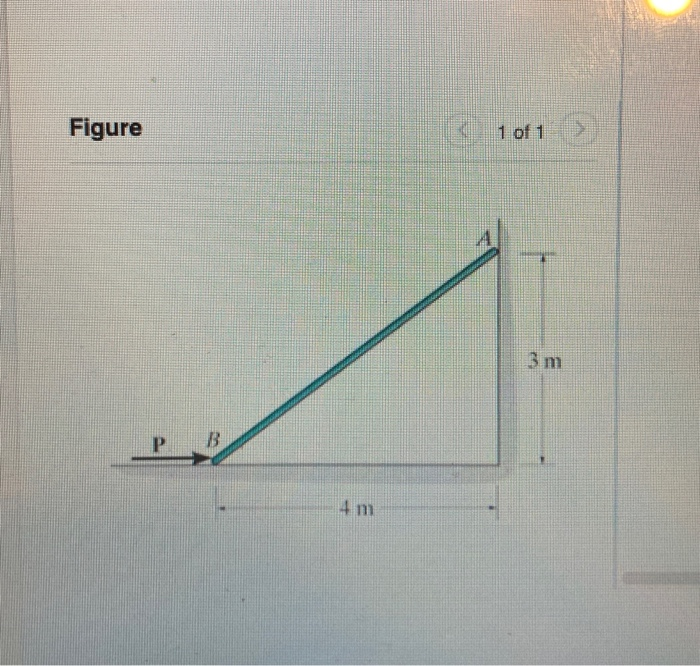
Question: Draw a free-body diagram of the rod AB. Assume the contact surface at B is smooth. Draw the vectors starting at the appropriate black dots. The location and orientation of the vectors will be graded. The length of the vectors will not be graded. Determine the minimum force P to prevent the 34-kg rod AB from sliding.
Vssut Ac In
Figure 5.32 (a) The free-body diagram for isolated object A. (b) The free-body diagram for isolated object B. Comparing the two drawings, we see that friction acts in the opposite direction in the two figures. Because object A experiences a force that tends to pull it to the right, friction must act to the left. Because object B experiences a component of its weight that pulls it to the left ...

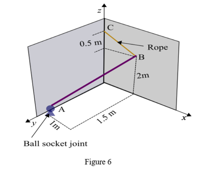
The Uniform 10 Kg Rod Ab Is Supported By A Ball And Socket Joint At A And By The Cord Cg That Is Attached To The Midpoint G Of The Rod Knowing That The Rod
FREE-BODY DIAGRAMS (Section 5.2) 2. Show all the external forces and couple moments. These typically include: a) applied loads, b) support reactions, and, c) the weight of the body. Idealized model Free-body diagram (FBD) 1. Draw an outlined shape. Imagine the body to be isolated or cut "free" from its constraints and draw its outlined shape.
System Isolation And Equilibrium Conditions Ppt Download
Draw a free-body diagram of the rod AB.Assume the contact surface at B is smooth.. b) Determine the minimum force P to prevent the 38-kg rod AB from sliding. The contact surface at B is smooth, whereas the coefficient of static friction between the rod and the wall at A is ?s = 0.22.
Rose Hulman Edu
PROBLEM 303: The uniform rod weighs 420 lb. and has its center of gravity at O. Draw a FBD of the rod. Neglect the thickness of the rod and assume all contact surfaces to be smooth. 45º Cable 2 ft. 4 ft. 2 ft. B A O
12 2 Examples Of Static Equilibrium University Physics Volume 1
A 20-lb force is applied to the control rod AB as shown. Knowing that the length of the rod is 9 in. and that the moment of the force about B is 120 lb · in. clockwise, determine the value of .. SOLUTION Free-Body Diagram of Rod AB: αθ=−25 ° Q =(20 lb)cosθ and MQ B = ()(9 in.) Therefore, 120 lb-in. (20 lb)(cos )(9 in.) 120 lb-in. cos 180 ...
Chapter 6 Drawing A T Free Body Diagram
4.52 Rod AB is acted upon by a couple M and two forces, each of magnitude P. (a) Derive an equation in e, P, M, and I which must be satisfied when the rod is in equilibrium. (b) Determine the value of corresponding equilibrium when M = 150 N m, P = 200 N, and I 600 mm. Fig. P4.52
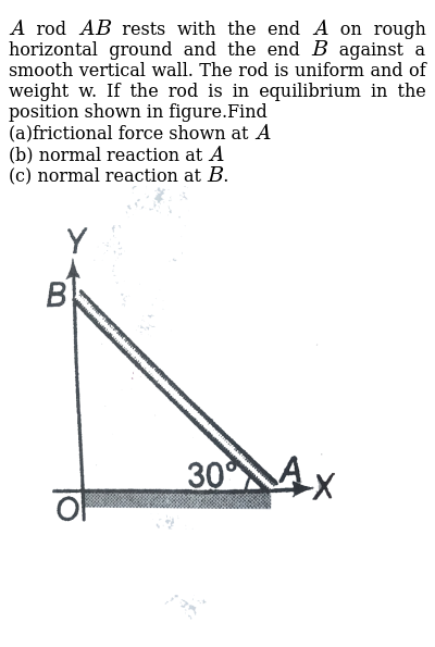
A Rod Ab Rests With The End A On Rough Horizontal Ground And The End B Against A Smooth Vertical Wall The Rod Is Uniform And Of Weight W If The Rod
The uniform rod weighs 420 lb and has its center of gravity at G. (a) Draw a Free-Body Diagram of the rod and determine the (b) Tension on the cable and (c) Reactions at the contact surfaces. Neglect the thickness of the rod and assume all contact surfaces to be smooth.
Vssut Ac In
The problem can be solved by considering segment AB, which does not involve the support reactions at C. Free-Body Diagram.The x, y, z axes are established at B and the free-body diagram of segment AB is shown in Fig. 1-8b.The resultant force and moment components at the section are assumed to act in
Solved 3 M P B 4 M A Review Draw A Free Body Diagram Of Chegg Com
Free-Body Diagram: For no motion, reaction at . A must be downward or zero; smallest distance a for no motion corresponds to A = 0. + SM B = 0 200 150 150 50 200 300 0: ( )( ) ( ) ( )( ) ( )N mm N N mm mm- - + +a a A= A a = (200 20000- ) 300

3 Introduction To Equilibrium Pptx Equilibrium Of Force Systems U2022equilibrium U2013 The Term Used To Designate The Condition Where The Resultant Of A Course Hero
Examples of drawing free-body diagrams. To better understand how to draw free-body diagrams using the 3 steps, let's go through several examples. Example 1. A box is pushed up an incline with friction which makes an angle of 20 ° with the horizontal. Let's draw the free-body diagram of the box. The first step is to sketch what is happening:
Hibbeler Chapter5
Solved Equilibrium Of A Rigid Body Engineering Mechanics Statics And Dynamics 14th Physics Numerade

Ch 12 Static Equilibrium Elasticity
Link Springer Com
Solved Equilibrium Of A Rigid Body Engineering Mechanics Statics And Dynamics 14th Physics Numerade

Free Body Diagram Application Physics For K 12 Openstax Cnx

Draw A Free Body Diagram Of The Rod Ab Assume The Contact Surface At B Is Smooth Determine The Minimum Force P To Prevent The 28 Kg Rod Ab From Sliding The Study Com

Mechanical Engineering Ch 11 Friction 18 Of 47 Ladder Example 3 Of 4 Youtube
Engcivil20142 Files Wordpress Com
12 2 Examples Of Static Equilibrium University Physics Volume 1
Hibbeler Chapter5
Library Poltekpel Sby Ac Id
Site Iugaza Edu Ps
Solved Part A Draw A Free Body Diagram Of The Rod Ab Assume Chegg Com
Roneducate Weebly Com
Tutorialcircle Weebly Com
Problem 357 Equilibrium Of Non Concurrent Force System Engineering Mechanics Review At Mathalino
Lpuguidecom Files Wordpress Com
Engcivil20142 Files Wordpress Com
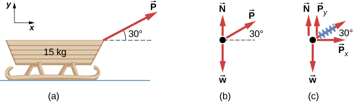
5 7 Drawing Free Body Diagrams University Physics Volume 1
Construccion Uv Cl
Solved Draw A Free Body Diagram On The Rod Ab Assume The Chegg Com
0 Response to "36 draw a free-body diagram of the rod ab. assume the contact surface at b is smooth."
Post a Comment