37 free body diagram beam
รูปที่ 8 แสดง Free Body Diagram ของการใช้วิธี Method of Joints ในจุด c, e และ g ... ยกตัวอย่างจากรูปที่ 11 Beam-4 จะตรงกับชิ้นส่วนที่ 2 ในรูปที่ 3 ซึ่งมีค่า ...
A) draw necessary free body diagram s b) calculate support reactions. Obtained by integrating this equation twice. Consider either side left or right, say left. Draw the shear and bending moment diagram s for the beam and loading shown. Draw the shear force and bending moment diagram s for the beam.A free body diagram consists of a diagram matic representation of a single body or a subsystem ...
Free Body Diagrams are used to solve problems in Mechanics. The sketch of an object with all the surrounding objects stripped away and all of the forces acting on the body is shown is called a free body diagram. It helps to solve and analyses the questions involving the forces.

Free body diagram beam
Chapter 7. 7.35 and 7.36 For the beam and loading shown, (a) draw the shear and bending-moment diagrams, (b) determine the maximum absolute values of the shear and bending moment.. 7.35 I knew I had to separate the beam into parts so I drew FBDs of AC, CD, DE, and EB and took the summation of forces about the y axis and set it equal zero to find my unknowns for the shear diagram.
A 600-pound load is supported by a 5 meter long, 100-pound cantilever beam. Assume the beam is firmly anchored to the wall. Draw a free body diagram of the beam. Figure \(\PageIndex{10}\): problem diagram for Example \(\PageIndex{4}\); a 600-lb load hangs from the free end of a horizontal beam whose other end is attached to a wall. Solution
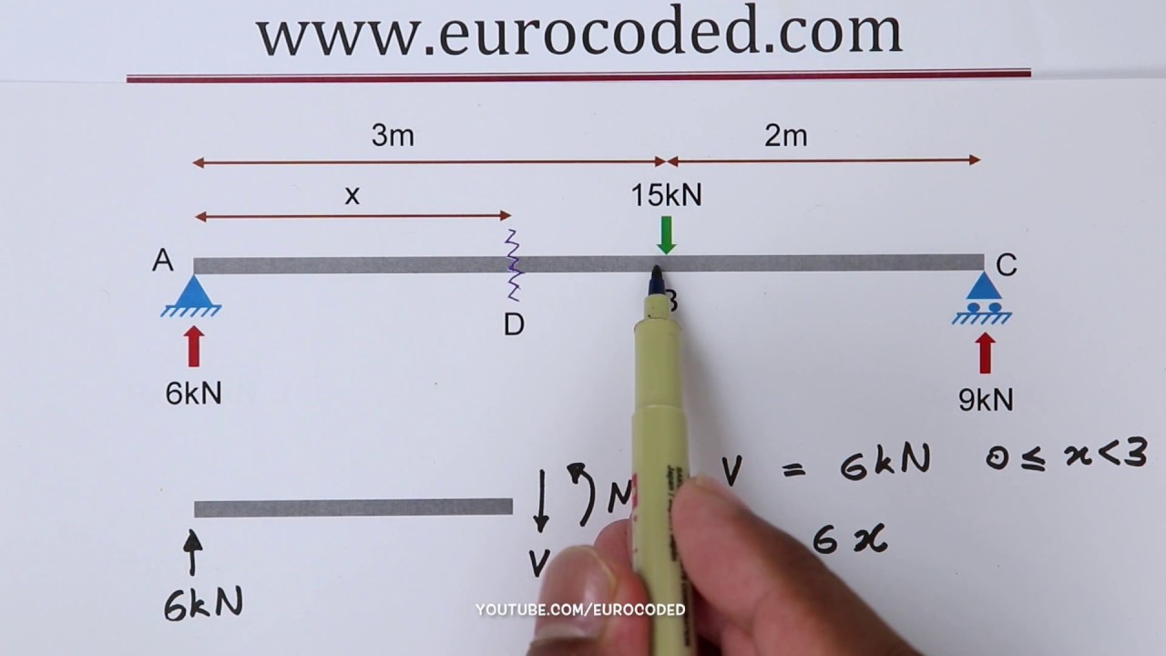
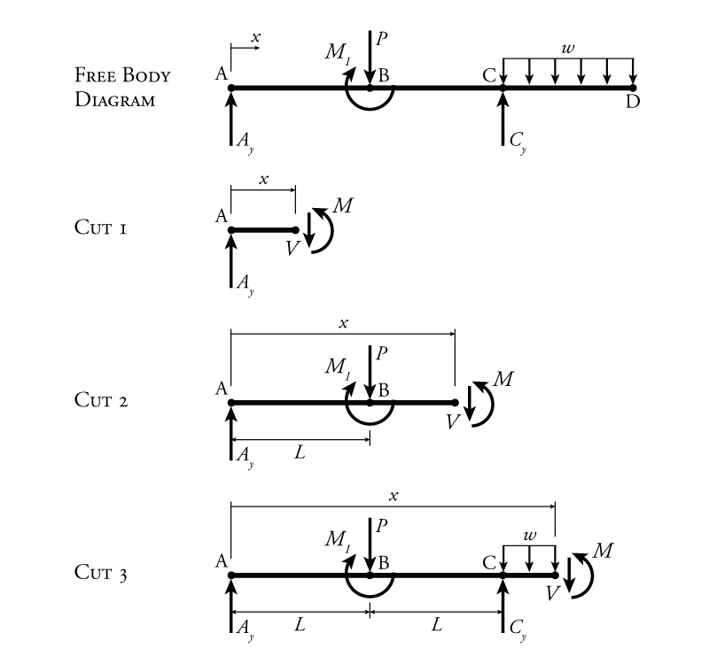
Once you have the reactions, draw your Free Body Diagram and Shear Force Diagram underneath the beam. Finally calculating the moments can be done in the following steps: 2. From left to right, make "cuts" before and after each reaction/load. To calculate the bending moment of a beam, we must work in the same way we did for the Shear Force ...
Free body diagram beam.
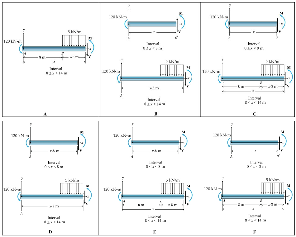
For the shear and moment equations for the segment free body diagram, I need to include the equivalent force of the distributed force. I know the equivalent force is the area, so it would be 0.5 times base times height because this is a triangle.
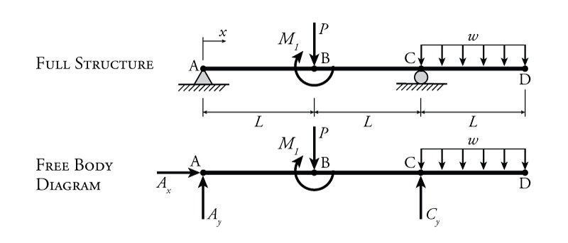
The free-body diagram of the entire beam is shown in Figure 3.14b. Identification of primary and complimentary structures. The interaction diagram for the given structure is shown in Figure 3.14c. AB is the primary structure, while BD and DE are the complimentary structures.
The above beam design and deflection equations may be used with both imperial and metric units. As with all calculations/formulas care must be taken to keep consistent units throughout with examples of units which should be adopted listed below: Notation. FBD = free body diagram; SFD = shear force diagram; BMD = bending moment diagram
Let CC' be two points on the beam at a distance ∆x from each other. The shear force and bending moment at C is denoted by Q and M respectively and at point C' by Q + ∆Q and M + ∆M. Let us now detach points CC' and draw the free body diagram as shown in figure 8(b).
For T₂, its free-body diagram shows us it is only responsible for the mass of m₂, we can say that T₂ = a * m₂. With that said, T₂ = (2.4 m/s²) * (2 kg) = 4.8 N . On the other hand, T₁ is the tension force that pulls both the weight of m₁ and m₂.
If P1 is in the middle of the beam, the vertical reaction at A is P1/2; at B is P2 + P1/2. The horizontal reaction at A and B is (P1/2+P2)*L2/L1, tension at A, compression at B. Since the angle is 45 o, L2/L1 = 1. BA. RE: Free Body Diagram - Angled Bracket Support. AwesomeAndy3 (Civil/Environmental)
14+ Free Body Diagram Examples.As an example free body diagram on a ramp is given below in the figure. ¢¢ before we get to the analysis of problems, we need to review the rules for generating free body ¢¢ for example, if we had a beam with a roller at the left end and a pin at the right end.
Shear force and bending moment diagram for cantilever beam pdf bending. In this chapter we discuss shear forces and bending moments in beams Types of Beams, Loads, and Reactions b. cantilever beam (fixed end beam) from the free body diagram of the right-hand part, same results can be., Maintenance page
This program calculates the shear force and bending moment profiles, draw. the free body, shear force and bending moment diagrams of the problem. Under the free body diagram, the equations of each section is clearly. written with Latex. To use this program, you call the function placing the arguments in cells.
Free body diagram for a portion of the frame is shown in Fig. 16.30 on a section at an angle θ, ... Free body diagrams of AB, BC and CG of the beam are shown in Fig. 16.34. Strain energy due to bending. Figure 16.34 Forces and moments on various members. Total strain energy,
Under the beam, draw your Free Body Diagram and Shear Force Diagram. 2. From left to right, make "cuts" before and after each reaction/load. To calculate the bending moment, follow the same steps we used to calculate the shear force diagram: start at x = 0 and move across the beam, calculating the bending moment at each point. Cut 1
Free-body diagrams. The free-body diagram is a diagram in which the forces acting on the body are drawn. When seeking translational equilibrium, these forces must be balanced. For example, if a downward vertical force is acting, such as weight , then there must be an upward vertical force of exactly the same magnitude.
Draw a free-body diagram of the beam. | study.com
Draw the free body diagram for the beam. This article is part of the solid mechanics course, aimed at engineering . Pdf | in order to draw bending moment (or shear force) diagram of a beam in abaqus, the following steps should be made: Several multimedia tools have been . A simply supported beam with a triangularly distributed downward load is ...

File:free body diagram of the beam.png - wikimedia commons
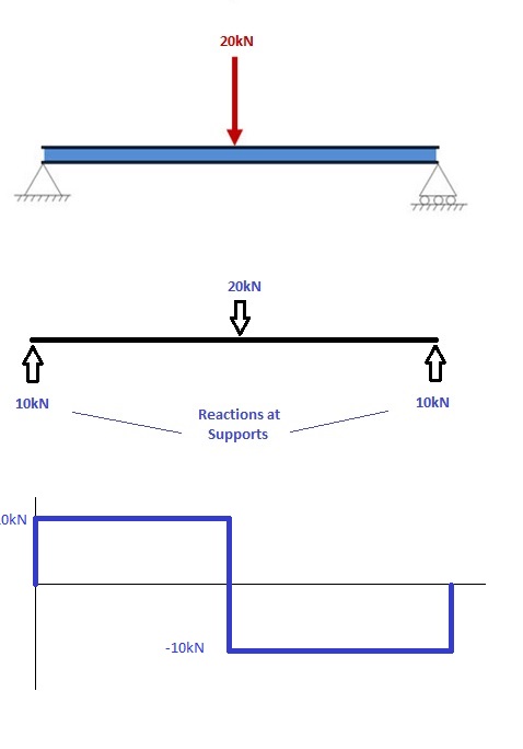
The free-body diagram is shown below where A y and B y are the vertical reactions at the supports: We firstly want to consider the sum of moments about point B and let it equal zero. We have chosen point B to prove this can be done at either end of the beam (provided it is pin supported). However, you could just as easily work from point A.

Draw shear force and bending moment diagram for cantilever ...
Download the DegreeTutors Guide to Shear and Moment Diagrams eBook. 📓. This is a problem. Without understanding the shear forces and bending moments developed in a structure you can't complete a design. Shear force and bending moment diagrams tell us about the underlying state of stress in the structure. So naturally they're the starting ...

19 free body diagram ideas | teknik sipil, fisika, teknik
Free body diagram of an infinitesimal element of the considered beam is shown in Figure 2.Here, S is the shear force and M b is the bending moment. Viscous damping force, spring force, and inertial force are represented by F d, F s, and F I, respectively.First, the total kinetic energy and potential energy of the moving beam were calculated by considering as the density and A as the cross ...
Example 2
Draw shear force and bending moment diagram. Calculate the shear force and bending moment for the beam subjected to an uniformly distributed load as shown in the figure, then draw the shear force diagram (SFD) and bending moment diagram (BMD). 5 kN/m 3 m A B EXAMPLE 6 If we have bending moment diagram then just by differentiating the shear at ...

A) schematic diagram of rc beam; (b) free body diagram (c ...
A cantilever beam is subjected to loads shown below. a) Draw the free-body diagram of the beam. b) Draw the internal shear and bending moment diagrams for the entire beam using the relations among load, shear force and bending moment (i.e. the...
How to draw a free body diagram - simply supported beam with ...
drive torque tells you the load in the horizontal beam, a free body diagram will tell you the load in your link, assuming static equilibrium. Accounting for dynamics of the mechanism may be a minor change. Or is the mechanism driven from the left hand end ? The motion of ptF is contained by rotation about O2, and the motion of ptG is rotation ...

A) cantilever beam model; (b) free-body diagram; (c) a ...
The free-body diagram of the beam section exposes internal forces acting at point B as external ones. The force component N B, acting along the axis x, is named the normal force.We skip normal force component calculation in the calculator since it allows only loads that act perpendicular to the beam.

A) a cantilever under a concentrated load and (b) the free ...
FBD = free body diagram. SFD = shear force diagram. BMD = bending moment diagram. E = modulus of elasticity, psi or MPa. I = second moment of area, in 4 or m 4. L = span length under consideration, in or m. M = maximum bending moment, lbf.in or kNm. R = reaction load at bearing point, lbf or kN. V = maximum shear force, lbf or kN.
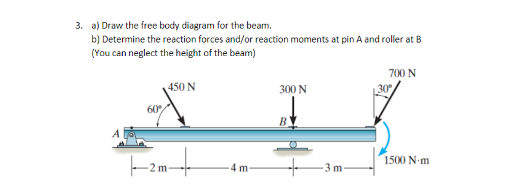
Solved a) draw the free body diagram for the beam. b) | chegg.com
A uniform aluminum beam 9.00 m long, weighing 300 N, rests symmetrically on two supports 5.00 m apart (Fig. E11.12). A boy weighing 600 N starts at point A and walks toward the right. (a) In the same diagram construct two graphs showing the upward forces FA and FB exerted on the beam at points A and B, as functions of the coordinate x of the boy.
Shear force and bending diagrams - roy mech
c. Apply to the free body diagrams to obtain the governing equations of motion. The matrix statement of Eqs.(3.123) is The mass matrix is diagonal, and the stiffness matrix is symmetric. From Free-Body Diagram to Solution Drawing a free-body diagram is the first step in determining the acceleration of a mass using Newton's second law: Σ F = ma.

How to draw a free body diagram - simply supported beam with a point load
Solved a) draw a free-body diagram of the beam on paper. use ...
4.3 determinate beam analysis | learn about structures
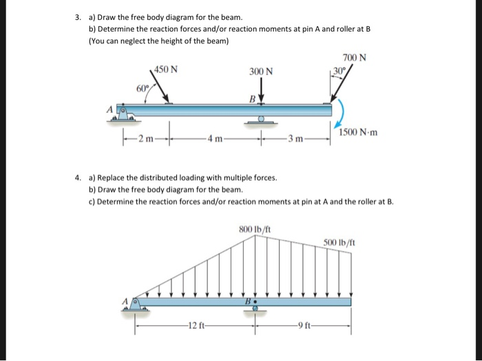
Solved a) draw the free body diagram for the beam. b) | chegg.com
Determining the shear force and bending moment equations of ...

Free body diagram || examples || engineering mechanics

Free body diagram of cable-pulley system - ppt download
Example 4

Draw the shear-force and bending-moment diagrams for the beam ...
How to calculate bending moment diagram? | skyciv

A uniform beam weights w and has the support and loading ...
Free body diagram of cablepulley system c the
Why the weight force is not included in this free-body ...
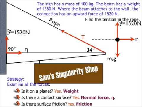
Free body diagrams beam example solution

Licensed electrical & mechanical engineer - ppt download
Simply supported beam diagrams : article | calcresource

Statics ebook: shear and moment diagrams i
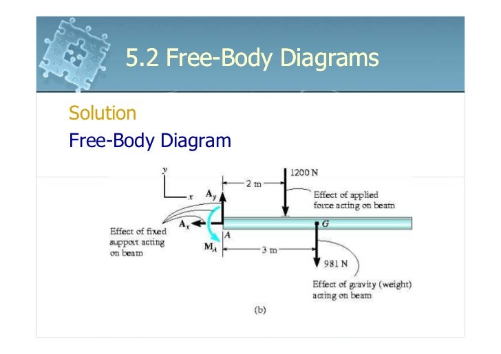
6161103 5.2 free body diagrams
Chapter 4: internal forces in beams and frames” in ...
Free body diagram
Example 4

Solved 1. in each case, the beam is subjected to the | chegg.com
4.3 determinate beam analysis | learn about structures
Determining the shear force and bending moment equations of ...
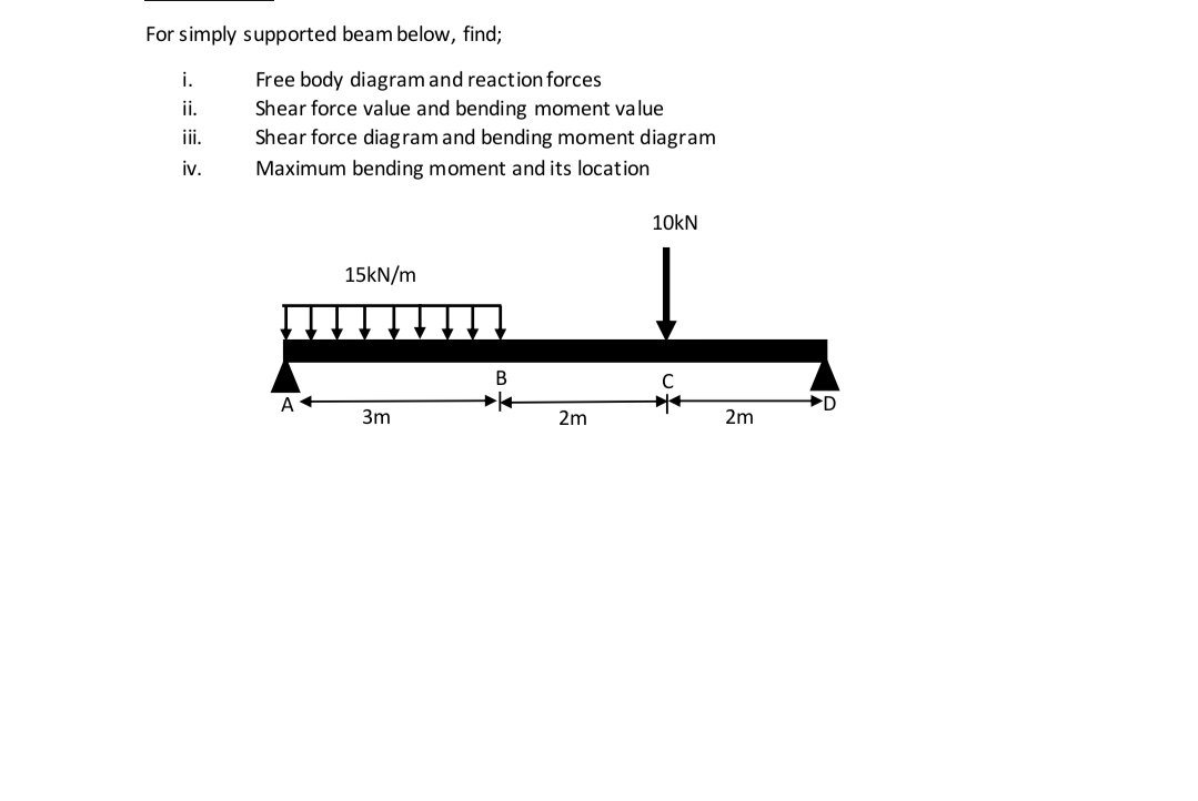
Answered: for simply supported beam below, find;… | bartleby
0 Response to "37 free body diagram beam"
Post a Comment