35 boat lift switch wiring diagram
Bremas Boat Lift Switch Wiring Diagram Elegant Bremas Drum Switch Sample. Click here to see other images of bremas switch wiring diagram. The following procedure is for wiring the already wired drum switch* to the motor using 14/5 Bremas # CYS2R, Bremas # CYS2R, Furnas. schematron.org: BH-USA Bremas Brand Boat Lift Switch Spring: Sports for easy wiring and directions for most Brands of boat ... The wiring diagram to the right will show how to wire and power this 12V 20AMP (ON)-OFF-(ON) 3 way Carling Contura rocker switch. When wiring this switch you can choose if you'd like to illuminate it because of the independent lamp attached to terminals 8 and 7. Or these terminals can be ignored for non-backlit switch banks.
A boathouse lift uses a hoist, cables, and pulleys to lift a boat. The boat hoist turns a pipe upon which the cable is wound, and the cable extends to the sides of the boathouse, travels down via pulleys, and then attaches to either slings or a cradle. SLINGS AND CRADLES Boathouse lifts use either polyester slings or steel cradles to lift a boat.

Boat lift switch wiring diagram
Boat Lift Switch Wiring Diagram. Variety of boat lift switch wiring diagram. A wiring diagram is a simplified traditional pictorial representation of an electrical circuit. It shows the parts of the circuit as streamlined forms, and also the power as well as signal connections between the tools. A wiring diagram typically offers info about the… Wiring Diagrams for Electric Motors & Controls. AMS Wiring Instructions. Instructions for AMS motors of both types (color coded wire-to-wire and yellow -wire) & AMS Reversing Switch. GEM 115V. Instructions for AMS motors using GEM Remote @ 115V. GEM 230V. 5. Wiring Motor #2: There are bundled wires coming off the level switch labeled "Motor #2 leads". Attach the motors red, black and orange wires color to color with these leads using wire nuts. Finally, connect the green wire from motor #2 to the green wire from the GEM control's ground. 6.
Boat lift switch wiring diagram. Leeson/Electra Gear c-face frame boat lift motor 110v wiring instructions with Bremas switch and GFCI. Today I want to show you how to wire a boat lift motor with this easy tutorial. Boat lift motor wiring can be a daunting process for new boat owners, but thi... INSTALLATION For the typical boat lift the installation is very straight forward using color-coded wiring diagrams and step by step instructions. It usually takes about an hour to two hours depending on how you are mounting the box and if you need to reconfigure your motor's wiring. Bremas Maintained Boat Lift Switch. The Bremas Maintained Boat Lift Switch stays in position until it is manually turned off. The lock-on switch features a durable molded plastic housing and a gasket sealed box. UL, NEMA, CE, SA compliant. Easy to wire terminals with locking screws. Wiring directions for most brands of boat hoist motors included.
DOWNLOAD. Wiring Diagram Sheets Detail: Name: bremas boat lift switch wiring diagram - Wiring Diagram For Boat Lift Motor Refrence Ao Smith Motors Wiring. File Type: JPG. Source: piotomar.info. Size: 1.02 MB. Dimension: 1583 x 2048. DOWNLOAD. Wiring Diagram Sheets Detail: Name: boat lift motor wiring diagram - Boat Lift Motor Wiring Diagram Intended For Switch 2002 Yukon Stereo Car Dimensions 2 Post; File Type: JPG; Source: nhrt.info; Size: 60.28 KB; Dimension: 576 x 279 Boat lift switch, single phase, momentary, 2 pole, 1.5HP at 120 Vac, 2HP at 240 Vac, Front Mounted Red Handle, labels, and IP65 Enclosure, UL508 Listed The ASI P0202500S-RH-EKIT is a 2 pole single phase boat lift switch used to reverse direction of a single motor ranging from 1.5HP to 2 HP. This Bremas Boatlift motor drum switch is found on most boatlifts and comes as a If you need a wiring Diagram to install your Boat Lift Motor to any of our Boat. The following procedure is for wiring the already wired drum switch* to the motor using 14/5 Bremas # CYS2R, Bremas # CYS2R, Furnas.
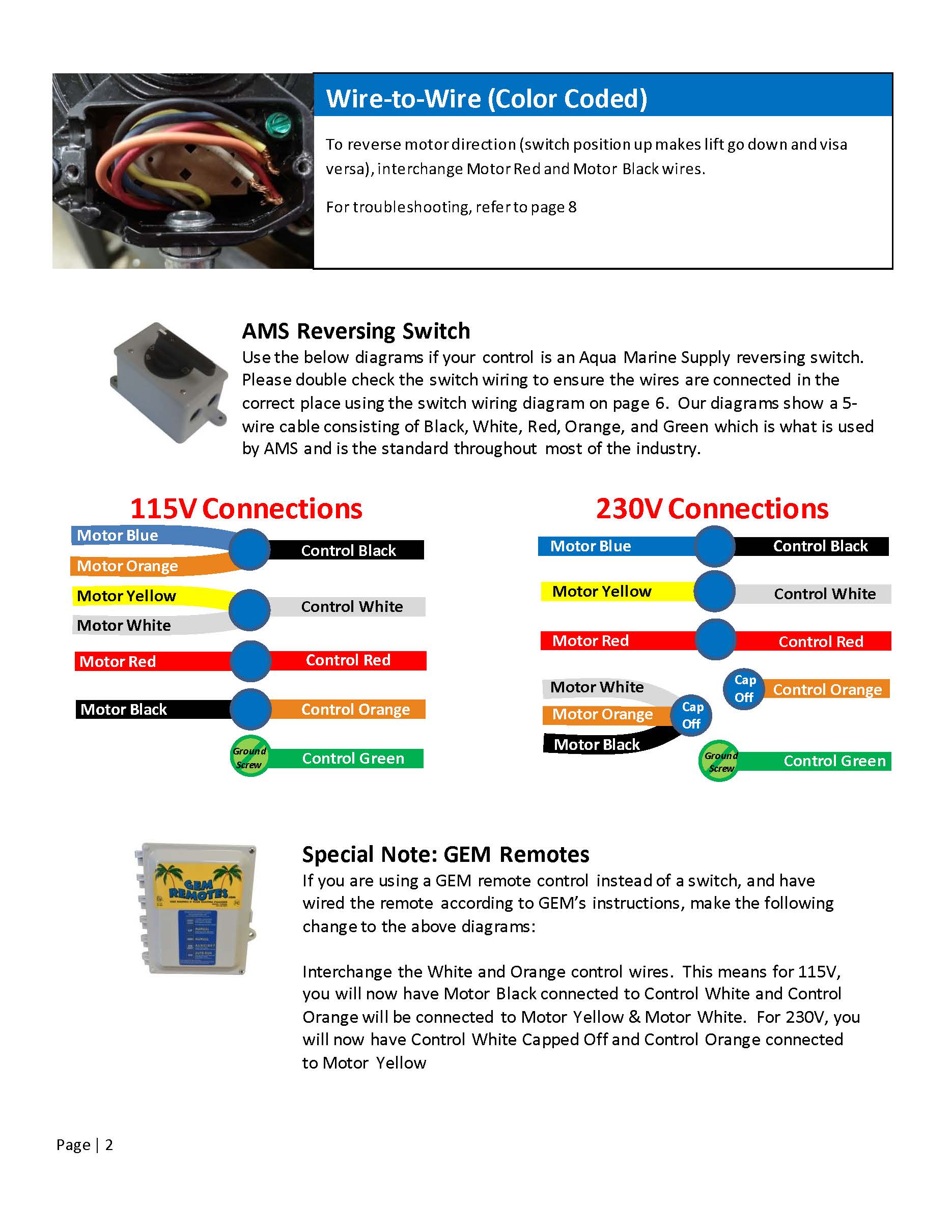
AMS Reversing Switch Use the below diagrams if your control is an Aqua Marine Supply reversing switch. Please double check the switch wiring to ensure the wires are connected in the correct place using the switch wiring diagram on page 6. Our diagrams show a 5-wire cable consisting of Black, White, Red, Orange, and Green which is what is used furnas switch wiring diagram. click here to view. 48 frame wiring diagram. click here to view. 56 frame wiring diagram. click here to view. wire to wire diagram: colored wires. click here to view. wire to wire diagram: t-wires. click here to view. qabl installation instructions. your source for quality boat lifts. This has been harder than I thought. I have a 120 volt motor that started tripping the gfi receptacle on my boat lift so I had an electrician run all new wire to the motor and new gfi's. still tripping the gfi so I bought a new motor, and a new drum switch. Then I found out it would trip the gfi... Motor Reversing Switch Single Phase Momentary 2 Pole 1.5 HP at 120 VAC 2HP at 240-Volt AC Boat Lift Switch for 1.5 HP motors at 120-Volt Boat Lift Switch for 1.5 HP motors at 120-Volt AC or 2 Horse Power motors at 240Vac. Designed for Outdoor use and can be mounted Vertically or Horizontally. Includes at IP65 Enclosure, Switch, Labels and Red ...
Based on the files we took from adwords, boat lift switch wiring diagram has a lot of search online web engine. We believe that boat lift switch wiring diagram present fresh thoughts or . A. Customer reviews. O. Smith boat lift wiring diagram for a furnas reversing switch - AO Smith A O Smith Motors Century 1hp question.

ASI Boat Lift Switch, Single Phase, Momentary (Spring Return) - for 1HP to 2HP Electric Motors. P0202500S-RH-EKIT
Boat Lift Switches are less-complicated boat lift remotes. Most commonly used with a switch handle that will either raise or lower the boat lift. These switches wire directly to the boat lift motor for operation. Optional mounting plates and wiring harnesses are available.
sales@tidetamer.com 800.325.1116 www.tidetamer.com Manual Switch WIRING DIAGRAM 110V & 220V WIRING 120V INCOMING POWER SUPPLY 220V INCOMING POWER SUPPLY WARNING: All electrical components should be wired by qualified personnel.
The following procedure is for wiring the already wired drum switch* to the motor using 14/5 control cable supplied by BH-USA. 1. REMOVE MOTOR CONNECTION BOX COVER. 2. CONNECT SWITCH BLACK WITH MOTOR WIRE TERMINAL 1 AND TERMINAL 3 WITH WIRE NUT. 3. CONNECT SWITCH WHITE WITH MOTOR WIRE TERMINAL 8 WITH WIRE NUT. 4.
Below is a list of commonly used motor and drum switch wiring diagrams and piling settings. If you have any questions or complications please call for assistance, 866-998-3625. BOAT LIFT US LIMITED WARRANTY. INSTALLATION INSTRUCTIONS: Up-N-Over Boat Lift US Lifts BOAT LIFT OPERATION & MAINTENANCE Boat Lift Operation . Boat Lift Maintenance
Wiring Diagrams Drum Switch GFCI Boat Hoist USA assumes no responsibility or liability for installations and/or improper use of the equipment. This guide is intended to be used as a reference and a general guideline only. Boat Hoist USA is not responsible for the design, construction or installation of docks, piers or lifts.
Connect Motor Black Wire to Switch Red Wire with wire nut Connect Orange Wire to Motor Terminal 2. ... Marathon and Electragear Motor wire procedures will ONLY work with these switches supplied by Boat Hoist USA. Salzer # P220-SE1518, Sal-zer # P220-SE1519, Bremas # CY0178099S2R, # CY0178068S2R, Furnas # D74756002, Furnas # ...
ROTARY LIMIT SWITCH with Wire (30ft of 18/3) $ 252.05. Add to cart. An electrical boat lift switch allows you to raise and lower your boat lift without any manual labor. Simply turn the switch and get your lift moving!
Bremas Momentary Boat Lift Switch. The Bremas Momentary Boat Lift Switch requires the user to hold the handle in place to lift or lower the boat. The spring-loaded switch will turn itself off when pressure is released from the handle. Features durable molded plastic housing and gasket sealed box. UL, NEMA, CE, SA compliant. Easy to wire switch.
Wiring Diagram for Salzer Reversing Drum Switch For use with 314 h", 1 hp, and 1.5 hp East Bay Motors GFCI Plug to Switch: Plug Black to Switch 1 White Plug to Switch 3 ( Wire-Nut to Switch Green ) Green Electric Cable from Motor to Switch: Red to # 4 Black to # 8 Orange to # 12 VN/hMtce to # 2 ( Wire-Nut to GFCI Green ) Green .
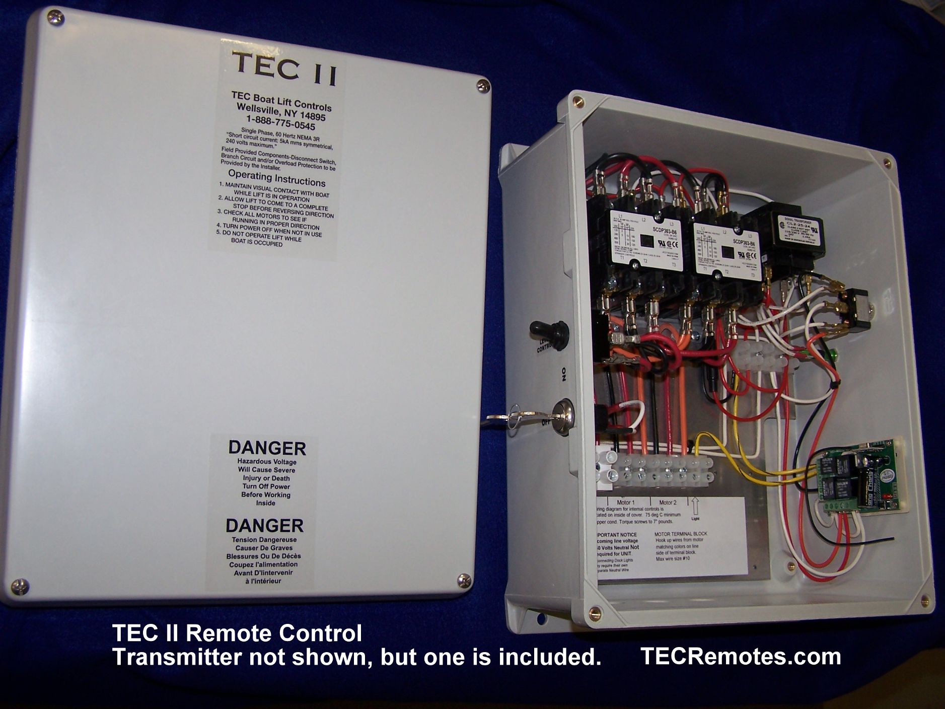
AMS/ AOS to Switch. Gem Remote to AMS-110 vOLT. Gem Remote to AMS-220 Volt. Gem Remote KAWIRE. Gem Remote Limit Switch Installation. TEC Limit Switch. TEC Wire Size Table. TEC Wiring Diagram & Motor Connections.
5. Wiring Motor #2: There are bundled wires coming off the level switch labeled "Motor #2 leads". Attach the motors red, black and orange wires color to color with these leads using wire nuts. Finally, connect the green wire from motor #2 to the green wire from the GEM control's ground. 6.
Wiring Diagrams for Electric Motors & Controls. AMS Wiring Instructions. Instructions for AMS motors of both types (color coded wire-to-wire and yellow -wire) & AMS Reversing Switch. GEM 115V. Instructions for AMS motors using GEM Remote @ 115V. GEM 230V.
Boat Lift Switch Wiring Diagram. Variety of boat lift switch wiring diagram. A wiring diagram is a simplified traditional pictorial representation of an electrical circuit. It shows the parts of the circuit as streamlined forms, and also the power as well as signal connections between the tools. A wiring diagram typically offers info about the…


0 Response to "35 boat lift switch wiring diagram"
Post a Comment