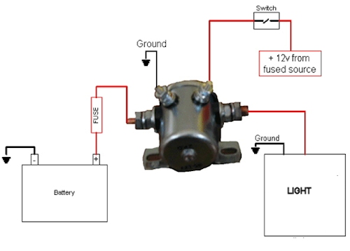
40 continuous duty solenoid wiring diagram
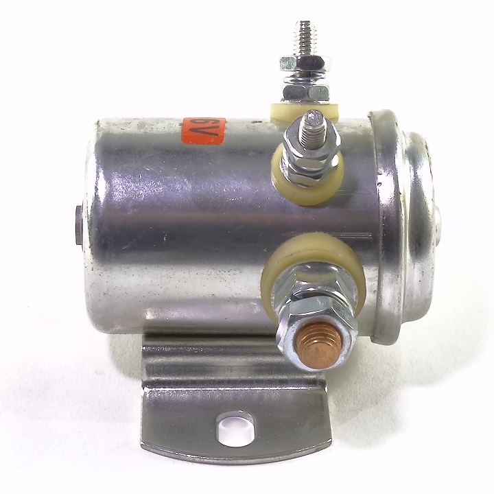
Pushframe Assembly (10' Super Duty) TFR07554 3 Pushframe Attachment Bar (Standard Duty) STB03203 Pushframe Attachment Bar (Super Duty) STB03231 Pushframe Attachment Bar (10' Super Duty) STB07547 BLADES 4 Blade (7'6" Standard Duty) STB03165 Blade (7'6" Super Duty) STB03166 Blade (8'0" Super Duty) STB03167 Blade (8'6" Super Duty) STB03168 Continuous Duty Solenoid 24V. An electromagnetic relay used in a direct current wiring system between a low current capacity switch and a high current load.
MaySpare Max 200A Trombetta Continuous Solenoid Relay 3 Terminal Heavy Duty Winch Marine 24106 SPST Solenoid 12VDC Rareelectrical New Cole Hersee 12 Volt 4 Terminal 200 Amp Continuous Duty Solenoid Compatible With Part Numbers 24213 24213BX 52-329 52329 70-906 70906 52329

Continuous duty solenoid wiring diagram
Tracing back on this circuit is fairly simple using a wiring diagram. The switches are activated in order: Reed switch, Forward and Reverse micro switch, key switch, Foot or pedal box switch. All of these switches must be working before the activation is delivered to one of the small posts (red wire). ElecDirect.com provides professional grade Electrical Connectors, Wire Management and Control Products to electrical contractors, OEMs, MROs and more. August 7, 2020 - We use cookies to personalize content, in our forums to recognize members and guests and their preferences, to complete web forms, to display third party ads, and to analyze our traffic. Personalized ads have been disabled for end users in the European Economic Area (EEA).
Continuous duty solenoid wiring diagram. Now that I should hopefully be done with internship interviews for the rest of my life, here's a mega list of almost every interview question I was asked from 150+ interviews at Facebook, Apple, Amazon, Nvidia, Google, Microsoft, Qualcomm, Analog Devices, Texas Instruments, Northrop Grumman, SpaceX, Tesla, etc. This is going to be a massive step up from ["part 1"](https://www.reddit.com/r/ECE/comments/iwmpw7/technical_internship_interview_questions_at_big/) that I posted a while back now that I... Continuous Duty Solenoid. An electromagnetic relay used in a direct current wiring system between a low current capacity switch and a high current load. This special solenoid toggles On and Off, and requires no current to maintain the continuity of the power circuit. Use it with a Mom function switch. Actuation of the momentary switch causes current to flow in the solenoid coil, locking the contact in place, maintaining the load circuit in ... The wiring diagram selector returns standard IQ3/IQT3 Range wiring diagrams only. For specials or if you can't find what you want, please contact Rotork.
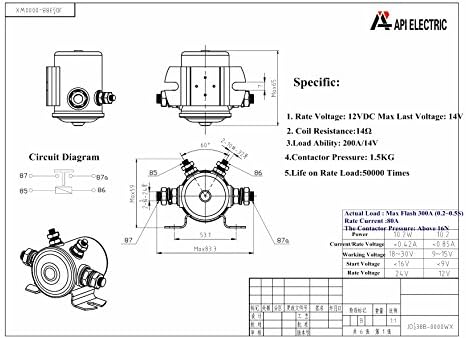
Dec 12, 2020 - Ford Starter Solenoid Wiring Diagram Kwikpik Me At Webtor Best Of Throughout At Ford Starter Solenoid Wiring Diagra, best images Ford Starter Solenoid Wiring Diagram Kwikpik Me At Webtor Best Of Throughout At Ford Starter Solenoid Wiring Diagra Added on Wiring Diagram – ... Need the Littelfuse equivalent to a competitor part? Enter the competitor part number here · Search for the part(s) number you wish to receive samples. Or, visit the sample center page January 4, 2019 - Hi all - I'm at the almost end of a very tedious and frustrating electrical install. Tedious and frustrating because my brain just doesn't comprehend how this stuff works. Don't worry, I have someone more experienced helping me so I don't blow anything up. I've purchased this solenoid and we... A solenoid in an electromagnetic relay used in a direct current wiring system between a low current capacity switch and a high current load requirement · 85A Continuous, 750A Make, 100A Break, 17.5 ohm
Max 300A Continuous Duty Solenoid Relay Nickel-Plating for Winch, Golf Carts, Marine in Rush 12VDC E-Z-GO Gas Marathon Models with 2 or 4-Cycle Engines by Lucky Seven 4.5 out of 5 stars 100 1 offer from $17.88 This process is automatic. Your browser will redirect to your requested content shortly · Please allow up to 5 seconds… Log In or Register Contact · Customer Support Phone: 866-746-3519 Email: ecommsalessupport@wesco.com · Menu Search · Cart -- · Search · ANIXTER IS NOW PART OF WESCO · Bringing you MORE+ of what matters. Learn More · WESCO IS OPEN FOR BUSINESS Free delivery on millions of items with Prime. Low prices across earth's biggest selection of books, music, DVDs, electronics, computers, software, apparel & accessories, shoes, jewelry, tools & hardware, housewares, furniture, sporting goods, beauty & personal care, groceries & just about anything else.
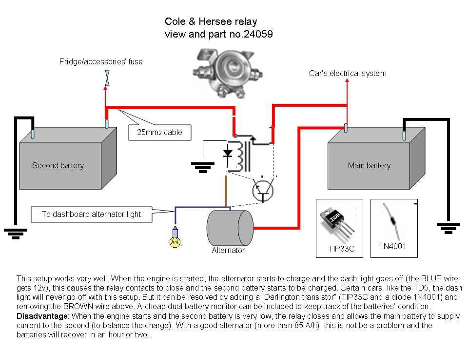
Like the title says, I'm wiring a continuous duty solenoid to charge my auxiliary battery, and I'm not sure which wire is my ignition wire. I need to splice into it so that the solenoid closes when it has signal from the ignition wire. Anyone out there have a wiring diagram or advice to offer?
March 9, 2021 - A starter solenoid is a critical part of your fleet vehicles' systems, as without it, you wouldn't be able to start your trucks. It takes a lot of power to start a vehicle, and a
Relay Devices Automotive Relays Continuous Duty Solenoids Remote Starter Solenoid High Power Relay Sealed Automotive Relay Relay Socket Relay Socket Kit Relay & Socket Assembly Mag Kill Solenoid EZ Mount Relay Board Relay Panel · #201-102 Use for battery switching or other applications that ...
I bought continuous duty solenoid, but I'm not sure I installed it correctly. Right now I have it mounted on the firewall, 4 gauge wire connecting …
September 19, 2020 -
Hey there. I'm designing my electrical system for my 2005 140" Sprinter. About a week ago I knew very little about electrical systems and since then I've gone balls deep in van electrical systems. I'm still not very confident that I have things done correctly, but I welcome any/all advice and feedback. I hope to run my loads off solar and alternator charging (no shore). I would like to boondock for 2-3 days at a time. If the suns not out, I don't mind alternator charging or minimizing my loads ...
Wiring Diagram Trailer Plugs and Sockets. Narva 7 and 12 pin trailer connectors comply with all relevant ADRs. Flat connectors comply with Australian Standards AS4177.5-2004. Large and small round connectors comply with AS2513-1982 while Heavy duty connectors meet the AS4735-2003 standard as required for vehicles and trailers over 3.5 tonnes.
Littelfuse is a global manufacturer of leading technologies in circuit protection, power control & sensing. Our products are found in automotive and commercial vehicles, industrial applications, data & telecommunications, medical devices, consumer electronics & appliances.
Way more users in this sub than the GMC sub, sorry for the x-post. Like the title says, I'm wiring a continuous duty solenoid to charge my auxiliary battery, and I'm not sure which wire is my ignition wire. I need to splice into it so that the solenoid closes when it has signal from the ignition wire. Anyone out there have a wiring diagram or advice to offer?
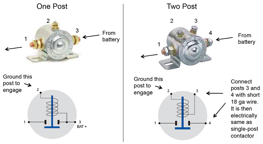
October 9, 2008 - Hey guys, need a little help here. I thought solenoids were simple, cant be that hard. Anyway, how is the wiring supposed to be? Of course there are 2 large terminals and 2 small terminals. 2 Large termsinals - Battery power and power to cell - Does it matter which one goes where?
Solenoids are cylindrical devices containing tight metal coiling within them. The devices are designed to convert electrical energy into mechanical power. Continuous duty solenoids are rated for 100 percent duty cycle.
So I understand the way a three wire control circuit works in terms of utilizing the start/stop button to energize the coil within the contactor to close all the NO contacts to NC. Going through Delmar's 5th edition Industrial Motor Control it brings up a simple manual starter utilizing a continuous-duty electrical solenoid. I understand that when line voltage is present the coil is energized closing the contact, when the line voltage is lost the contacts open and the coil is de-energized. And y...
May 22, 2019 - Starter Solenoid Wiring Diagram Luxury Reference Motorcycle Ignition For Motor At Starter Motor Solenoid Wiring Diagr, best images Starter Solenoid Wiring Diagram Luxury Reference Motorcycle Ignition For Motor At Starter Motor Solenoid Wiring Diagr Added on Wiring Diagram – ...
A sizing guide for electric actuators and manual gearboxes, that can be filtered via valve type and duty. Wiring Diagram Selector An easy to use tool for to find the correct wiring diagram for your product.
August 7, 2020 - We use cookies to personalize content, in our forums to recognize members and guests and their preferences, to complete web forms, to display third party ads, and to analyze our traffic. Personalized ads have been disabled for end users in the European Economic Area (EEA).
ElecDirect.com provides professional grade Electrical Connectors, Wire Management and Control Products to electrical contractors, OEMs, MROs and more.
Tracing back on this circuit is fairly simple using a wiring diagram. The switches are activated in order: Reed switch, Forward and Reverse micro switch, key switch, Foot or pedal box switch. All of these switches must be working before the activation is delivered to one of the small posts (red wire).













0 Response to "40 continuous duty solenoid wiring diagram"
Post a Comment