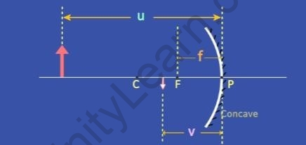
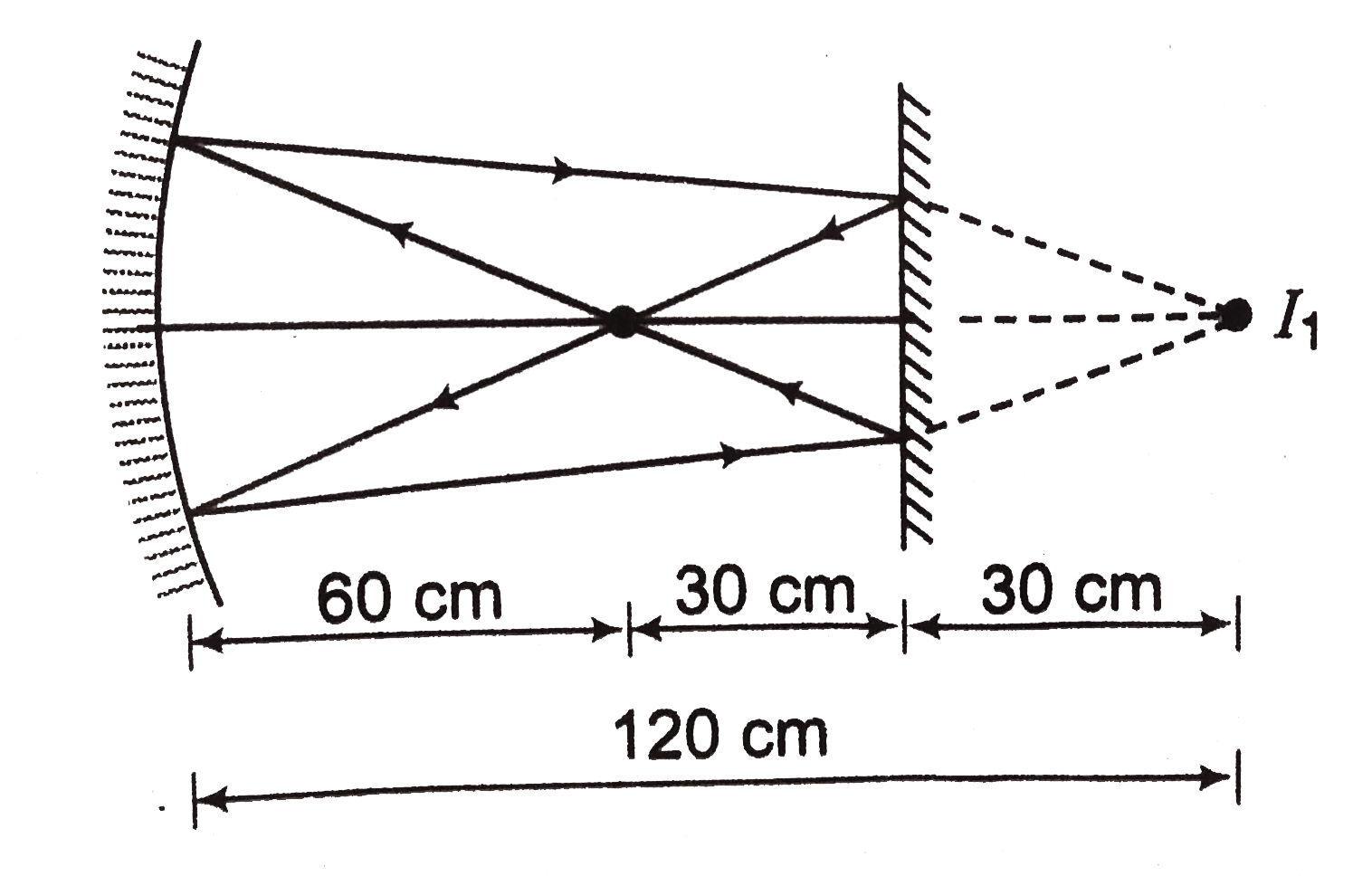
36 based on the ray diagram and distances shown in figure 1
What is Use Case Diagram? The figure below shows the UML diagram hierarchy and the positioning of the UML Use Case Diagram. As you can see, use case diagrams belong to the family of behavioral diagrams. Use case diagrams are based upon functionality and thus should focus on the "what" and not the "how". What is the difference between orthographic projection and... - Quora As shown...in figure-1. figure-2. Here the distance between observer & the object is finite. When the light falls on the object.. It gets reflected ...rays pass through the lens & .falls on the retina ...forms an image which is perceived by brain ...& the story u know!
"Exploring in UE4" game character movement... - Programmer Sought As shown in Figure 2-2. Figure 2-2 Class diagram of mobile component inheritance relationship. There are four mobile component classes. In addition, the current movement of Character is based on the capsule body, so an Actor without a capsule body component cannot use...

Based on the ray diagram and distances shown in figure 1
Physics Tutorial: Refraction and the Ray Model of Light The ray nature of light is used to explain how light refracts at planar and curved surfaces; Snell's law and refraction principles are used to explain a Any incident ray traveling parallel to the principal axis of a converging lens will refract through the lens and travel through the focal point on the opposite... (PDF) Efficient implementation of the 3D-DDA ray traversal algorithm... results show that the CCCS program based on our 3D-DDA implementation is. 1.42~2.67X faster than that based on METHODS. Ray traversal is a procedure of computing the propagation path of a ray in a given region. represents the distance along the ray when it traverses from one boundary plane to the 150. the 3D-DDA algorithm to traverse a ray in the 2-D space is illustrated in Figure 1. Note. PDF Studies of Polytype Silicon Carbide Produced Figure 1. State diagram of Si-C system [3]. There is a diagram of Knipenberga in Figure 3, which shows the temperature areas of the existence of individual polytypes. 2. Using X-ray structure analysis have been shown the difference between polytypic composition of industrial silicon carbide...
Based on the ray diagram and distances shown in figure 1. Electrical Engineering Recent Questions | Chegg.com Q: 2. Based on the circuit shown in Figure 2 below, calculate : current, ia dan is by using current divider law 9) With reference to the inductor charging circuit shown in the following figure, answer the following questions. | Assume the distance between the stub Calculate the length of short circ. A visual introduction to machine learning Based on the home-elevation data to the right, you could argue that a home above 73 meters should be classified as one in San Francisco. On the right, we are visualizing the variables in a scatterplot matrix to show the relationships between each pair of dimensions. PDF Software Requirements Specification | Figure 1 - Block diagram Figure 1 - Block diagram. The mobile application has some restrictions about the resource allocation. The result will be based on the criteria the user inputs. In Figure 5, the list view for the results is shown. When a user searches by price, this view should be the default one. K-Means Segmentation of Underwater Image Based on Improved... Based on the above analysis, this paper presents an improved algorithm for manta rays, which uses random walk learning to make individuals wander , the schematic diagram of Lévy flight is shown in Figure 1. Lévy flight can search long and short distances in a certain space and balance the global...
Figures and Charts - The Writing Center • University of North Carolina... Figures should be: Centered on the page. Labeled (under the figure) with the figure number and appropriate The chart shows the relative proportion of fifteen elements in Martian soil, listed in order from The graph shows the number of male and female spaceship crew members for five different... Ray Marching and Signed Distance Functions Points inside the sphere will have a distance from the origin less than the radius, points on the sphere will have This is where the ray marching algorithm comes in! Just as in raytracing, we select a position for the camera, put This diagram from WikiPedia shows what's possible with the technique Introducing Ray Tracing in Unreal Engine 4 | NVIDIA Technical Blog Ray tracing reflections. Figure 1. Note the reflection and how it bends around surfaces. The more you can tighten that up and cull them based on the distance factor, the better your scene performs. The NVIDIA RTX UE4 branch has additional optimizations to clamp the number of shadow casting... (anonymous) After 11. striking the lens shown in the diagram at right, the light ray will most likely follow which path? If the object distance for a converging thin lens is more than twice the focal length of the lens, the 19. image is. The figure shows five possible subsequent paths for the light ray. Where would the ray exit the layer of air if the glass was 34. replaced with a material of lower index of refraction?
Java 2D graphics | Think Java | Trinket Figure B.1: Diagram of the difference between Cartesian coordinates and Java graphical coordinates. To draw on the canvas, you invoke methods Modify the program so that the circles are drawn in the center of the screen and concentric, as in Figure B.5 (left). The distance between the circles should... PDF Topic 5a XRD Lectures.PDF | Detection of Diffracted X-rays The phenomenon is called X-ray diffraction. incident beam. Effect of sample thickness on the Crystals consist of planes of atoms that are spaced a distance d apart, but can be resolved into many atomic •Providing images that show the structure of materials •Producing X-rays with 108 more... Dijkstra's Shortest Path Algorithm - A Detailed and Visual Introduction The distance from the source node to itself is 0. For this example, the source node will be node 0 but it can be any node that you Select the node that is closest to the source node based on the current known distances. In the diagram, the red lines mark the edges that belong to the shortest path. Помогите пожалуйста с тестами по английскому языку which type of... Ответы а) currency б)fees в bonus г salary 2.The money paid for the use of house or flat Ответы a bills бrent в bonus г coins 3Choose the synonym of social security Ответы awelfare б tax в apartment г rent 4.What is a financial plan, showing how much money a person or organization?
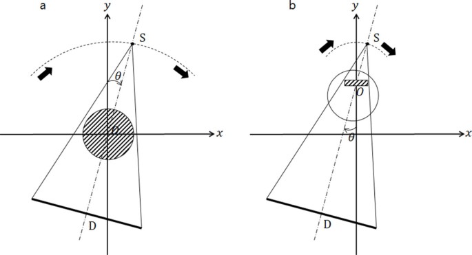
Quadratic cross-sections in the multiple scattering by a pair ...
Image Formation by Lenses | Physics Figure 3 shows a concave lens and the effect it has on rays of light that enter it parallel to its axis (the path taken by ray 2 in the Figure is the axis of the lens). The paths are exactly the reverse of those shown in Figure 1. This technique is used in lighthouses and sometimes in traffic lights to produce a...
Spherical Mirrors - Sign Conventions - Infinity Learn
Electronics | Free Full-Text | Commercial P-Channel Power... Figure 3 shows that the fitting of sensitivity using Equation (7) is good. The parameters of Equation (7), obtained as a result of fitting shown in Figure Taking into account the mechanisms of creating traps in the oxide during irradiation [31], it is absolutely clear that ∆Nft depends on the energy absorbed in...

Virtual Labs
UML 2 Class Diagrams: An Agile Introduction Figure 1. Sketch of a conceptual class diagram. Enrollment is an associative class, also called a link class Associative classes are typically modeled during analysis and then refactored into what I show in Figure 2 I was able to determine with certainty, based on this information, the multiplicities for all...

Ray Diagrams — Isaac Physics
How to Use Charts and Graphs Effectively - From MindTools.com Discover how and when to use charts and graphs, including Venn diagrams and pie charts, to "Graph" refers to a chart that specifically plots data along two dimensions, as shown in figure 1. Examples of trend data include how sales figures vary from month to month, and how engine...

Geometrical Optics 101: Paraxial Ray Tracing Calculations
Entity Relationship Diagram (ERD) Tutorial - Part 1 - YouTube Learn how to create an Entity Relationship Diagram in this tutorial. We provide a basic overview of ERDs and then gives step-by-step training on how to make...
Inter-plane artifact suppression in tomosynthesis using 3D CT ...
Spherical Mirrors - University Physics Volume 3 Use ray diagrams and the mirror equation to calculate the properties of an image in a spherical Consider rays that are parallel to the optical axis of a parabolic mirror, as shown in part (a) of The mirror equation relates the image and object distances to the focal distance and is valid only in the...
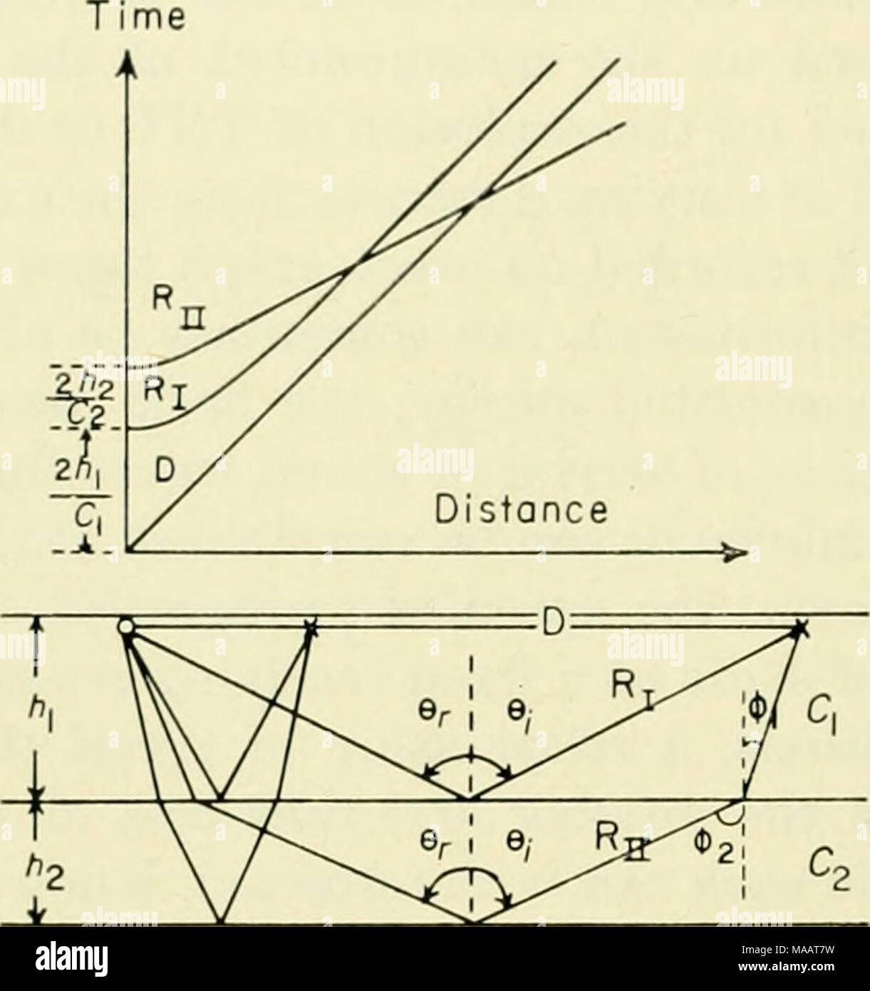
The Earth beneath the sea : History . Fig. 1. Ray diagram and ...
Graphing Calculator Explore math with our beautiful, free online graphing calculator. Graph functions, plot points, visualize algebraic equations, add sliders, animate graphs, and more.

Method designs free-form optical devices
Femtosecond diffractive imaging with a soft-X-ray free-electron laser Figure 1 shows our experimental arrangement. Diffractive imaging is elegant in its simplicity: a coherent X-ray beam illuminates the sample, and the far-field diffraction pattern of the object is The ultrafast coherent diffraction pattern of a nanostructured non-periodic object is shown in Fig. 2a.
P6 LENSES
optics - Inconsistency in ray diagram - Physics Stack Exchange This example purports to show reflection of light rays from a spherical mirror. It looks good, until you try to draw a ray from the tip of the candle flame, then Check out the link below which incorporates the ray you are questioning. Place the object roughly midway between C and F as in your diagram then...
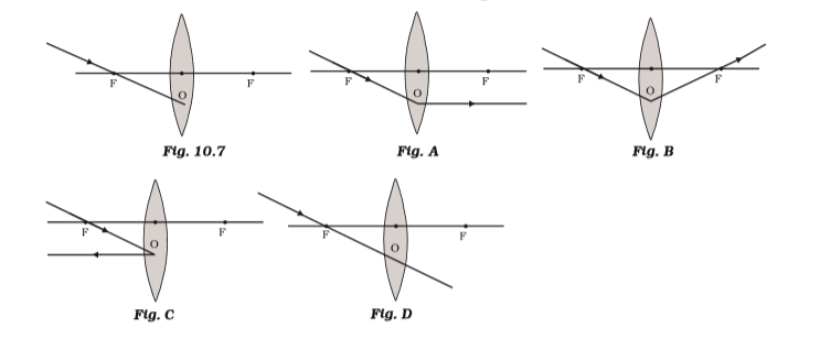
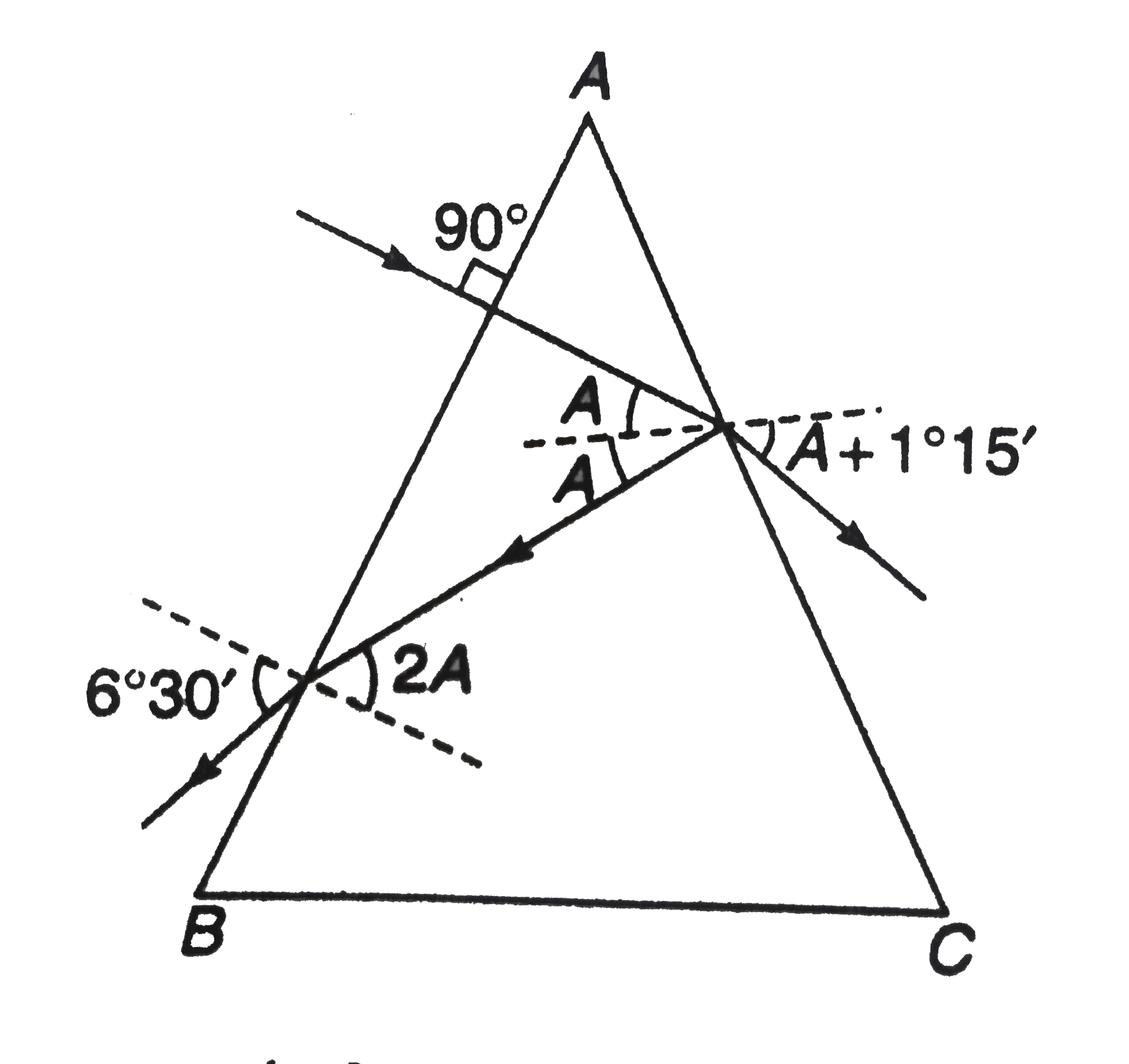
Which of the following ray diagrams is correct for the ray of ...
Rods & Cones The bottom figure shows the distribution of rods and cones in the retina. This data was prepared from Although not shown in this schematic, the columns are arranged in a circle like the planks of a This diagram was produced based on histological sections from a human eye to determine the...

Fundamental Shifts In IC Manufacturing Processes
PDF Physics-1 shown in Figure. For an axis perpendicular to. the rod, Show that the system has the. 9. Two blocks, as shown in Figure, are connected by a string of negligible mass passing over a pulley of radius 0.250 m and moment of inertia I. The block on the frictionless incline is moving up with a...
Applied Sciences | Free Full-Text | Swing Analysis and ...
Ray Marching | Michael Walczyk | Distorting the Distance Function The diagram below shows this process in action. Our first scene will be much simpler than this, but for illustration The last thing we need to figure out is, how do we generate our rays? You can play around with this effect: try using other combinations of sin and cos based on the coordinates of the...

Plasmon-enhanced photoluminescence from MoS2 monolayer with ...
PDF Studies of Polytype Silicon Carbide Produced Figure 1. State diagram of Si-C system [3]. There is a diagram of Knipenberga in Figure 3, which shows the temperature areas of the existence of individual polytypes. 2. Using X-ray structure analysis have been shown the difference between polytypic composition of industrial silicon carbide...
Sensors | Free Full-Text | A New Pattern Quality Assessment ...
(PDF) Efficient implementation of the 3D-DDA ray traversal algorithm... results show that the CCCS program based on our 3D-DDA implementation is. 1.42~2.67X faster than that based on METHODS. Ray traversal is a procedure of computing the propagation path of a ray in a given region. represents the distance along the ray when it traverses from one boundary plane to the 150. the 3D-DDA algorithm to traverse a ray in the 2-D space is illustrated in Figure 1. Note.
Test: Light: Reflection & Refraction- Case Based Type ...
Physics Tutorial: Refraction and the Ray Model of Light The ray nature of light is used to explain how light refracts at planar and curved surfaces; Snell's law and refraction principles are used to explain a Any incident ray traveling parallel to the principal axis of a converging lens will refract through the lens and travel through the focal point on the opposite...
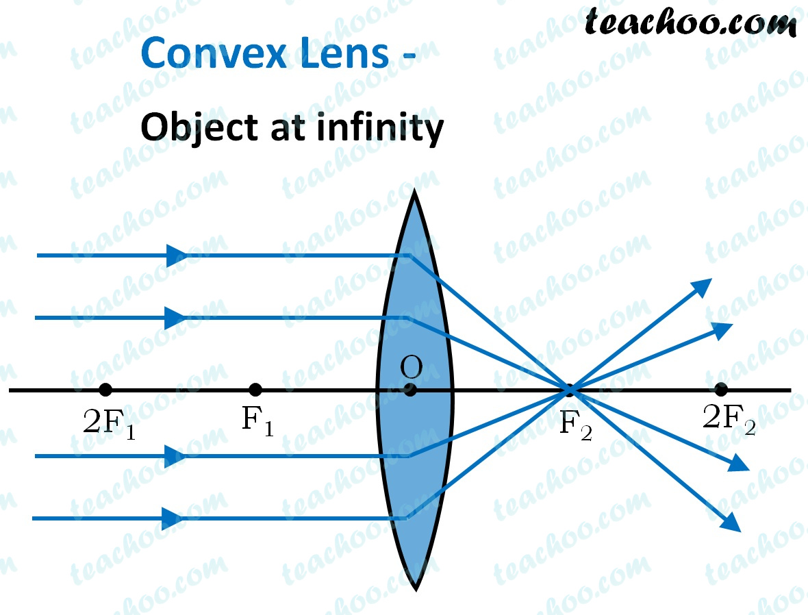
Convex Lens - Ray diagram, Image Formation, Table - Teachoo
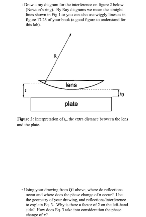
Solved Draw a ray diagram for the interference on figure 2 ...

How to handle optical design challenges in 3D imaging ...
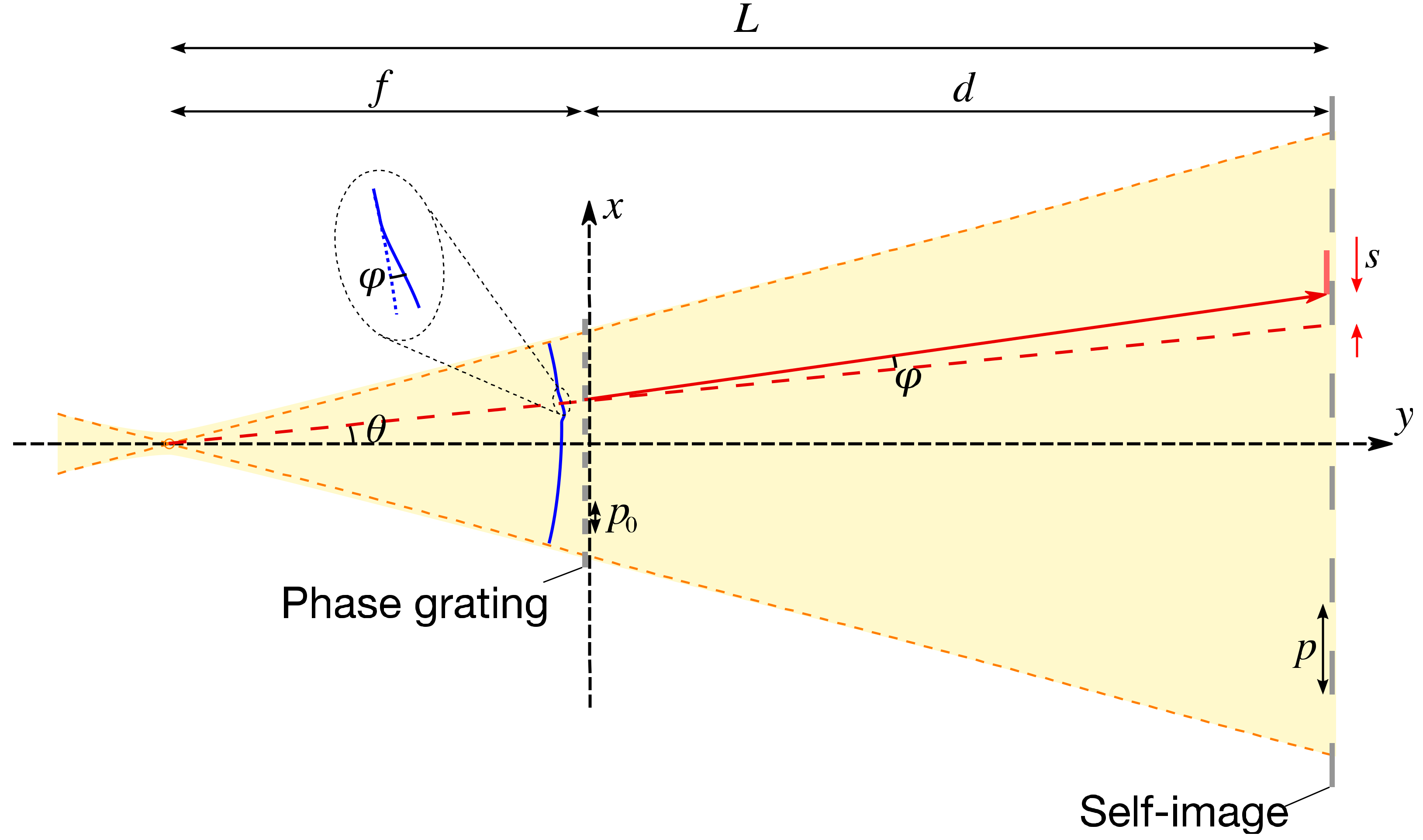
Sensors | Free Full-Text | X-Ray Single-Grating ...
arXiv:1702.03240v1 [quant-ph] 10 Feb 2017

Using 3D Laser Scanning Technology to Create Digital Models ...
0625 QR Dynamic Papers Physics ol Cambridge
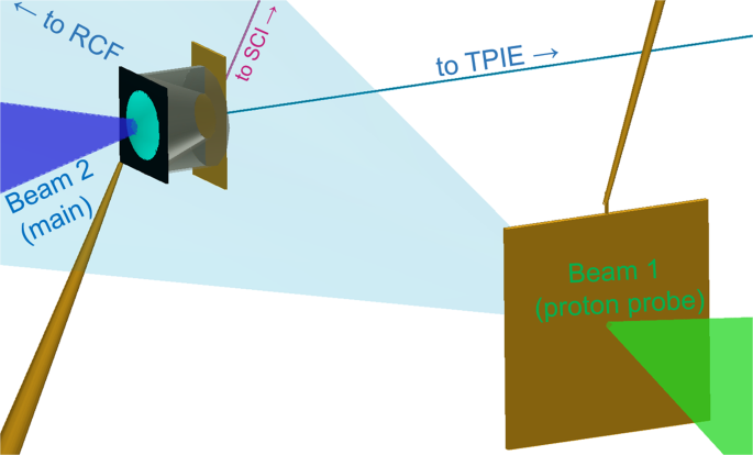
Focussing Protons from a Kilojoule Laser for Intense Beam ...
![SPOILER] AAMC Section Bank C/P #11 : r/Mcat](https://preview.redd.it/4pnf2v7yrcg21.png?width=1147&format=png&auto=webp&s=35833190a4eab9ade1422b9e3cd074f1f6aaee33)
SPOILER] AAMC Section Bank C/P #11 : r/Mcat
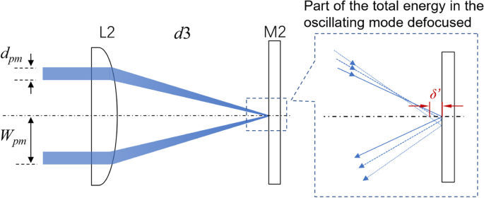
Intracavity spherical aberration for selective generation of ...
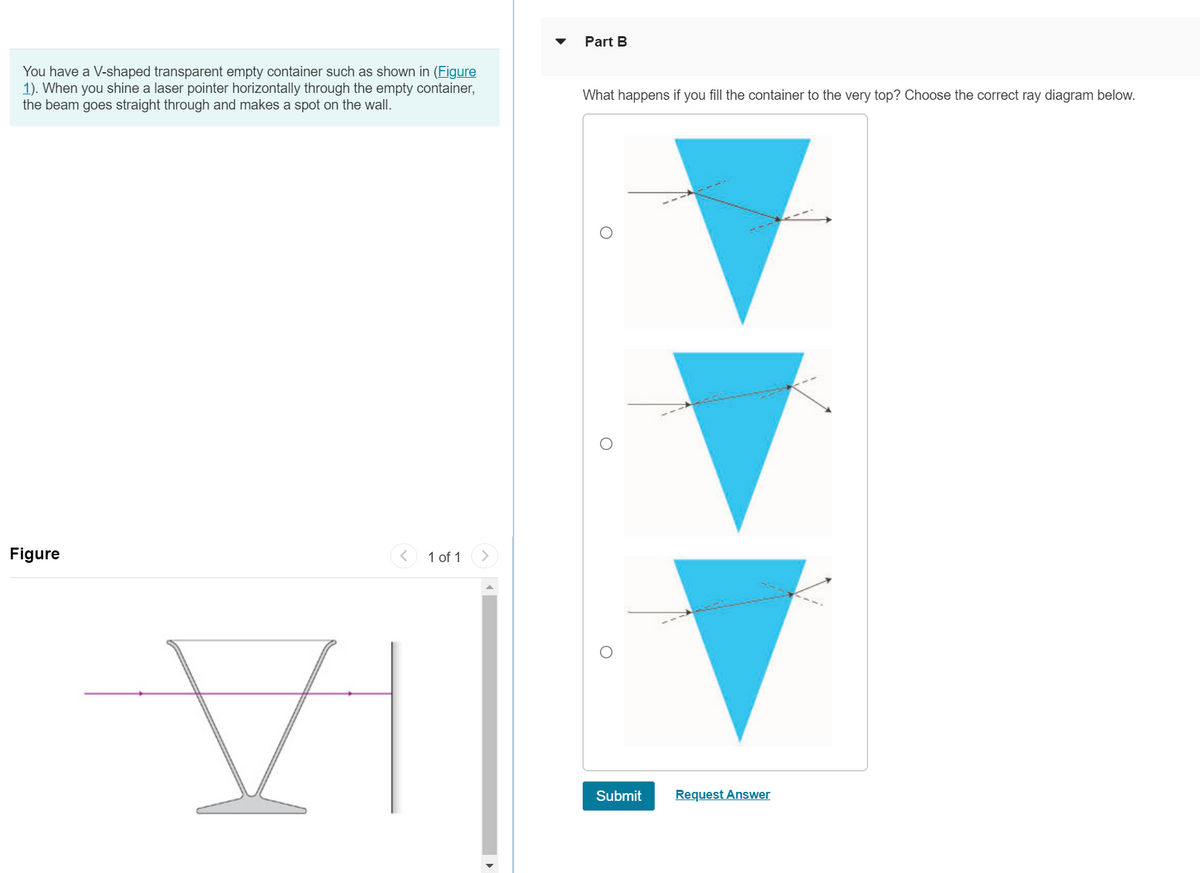
Answered: Part B You have a V-shaped transparent… | bartleby

Image Formation by Mirrors | Physics

Ray tracing 3D spectral scenes through human optics models ...

BIR Publications
A point source of light S is placed on the major optical axis ...

Graphical Optimization Method for Symmetrical Bidirectional ...
The figure shows an arrangement of an equi-convex lens and a ...

Hydraulics of Fluidized Cavities in Porous Matrices: Cavity ...
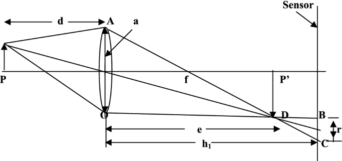
Lens calibration for obstacle detection | SpringerLink

q38-draw-a-ray-diagram-to-show | LIDO

Towards Controlling the Threading Direction of a Calix[6 ...
0 Response to "36 based on the ray diagram and distances shown in figure 1"
Post a Comment